20230508 Tuning In the O-Ring Size


Parker handbook 


4.3 Face Type Seals

“Face type seals are sometimes rectangular. In designing such

a seal to receive a standard O-ring, the inside corner radii of

the groove should be at least three times (ideally six times) the

cross-section diameter of the O-ring to avoid over-stressing

the ring or causing corner creases that would potentially leak.

The cross section of the o ring is 0.139 inches

The minimum internal bend radius is 3*0.139 = 0.417 


This had to be adjusted within the design

Page 4-18 in the parker handbook

Page 4-25 in the parker handbook

Diametral clearance. 


The O-ring we are looking for has a dash number of 255 


5.609 + 0.005 = 5.614

20230507 Blender Exploration of Camera Placement


Main changes, setting all of the fusion 360 models to meters before exporting. The FOV of the camera looks more realistic. 

Shift+s for moving 3d cursor to selected geometry

  • Allows us to import a camera directly onto the modeled camera within blender

Front view of where the grippers would go (small claw full extension) (large claw, restricted extension


Downward facing camera

Suggested view for the external camera


External camera pointed towards the gripper from the back of the sub

“shift  + h” isolate all except selected

“Alt + h” show all

“H” hide selected


Bottom facing camera with the larger gripper completely extended

Left: bottom view of the camera

Right: front view of the sub with the gripper extended all the way down


20230506 Playing around with FOV of the Camera in Blender


Importing sub into blender as a .obj model 


Zoomed in view of camera object in blender placed on modeled camera


Placing the 

Note “ctrl+L” to select the paired vertices, allows to delete the entire object in the blender obj file type


“Ctrl + alt + 0” locks the camera to current view

“0” change view to camera view


“5” changes from orthographic to perspective view

3 side view

9 opposite view (if looking bottom from top, switches to looking up from bottom)

7 top view


Be sure to click on the camera to bring up the camera properties


Utilizing the camera properties here


DFOV / HFOV / VFOV

81° / 69° / 55°

Using this forum post to size correctly here


Currently we see that the gripper is not in view of the camera when stowed

“Alt + z” for x ray view

“X” delete tool


Note when importing .obj files into blender set the model dimensions to meters, here the dimensions in blender scaled 1 inch to 1 meter


“Shift z” goes to wireframe


Side view with the lid mission about 25 inches from bottom of the sub. Note with the incorrect units while exporting from fusion to blender the FOV is incorrect.

This is what the bottom facing camera may see when the top of the bin is about 25 inches below the sub. Note not accounting for the color change from the water


Current settings of the camera: (note treating 1m as 1 inch and applying the proper conversions)


20230503 trying to implement solution that surrounds the existing solution


Reference here

AS568 Series

O-Ring Cross-Section

Gland Depth (D)

Squeeze

Gland Width (W)

Gap (H)

Gland Corner Radii


Nominal

TOL (+/-)


Actual

Percent

Nominal

TOL (+/-)

w/ 1 Backup Ring

w/ 2 Backup Rings

MAX

R1

R2

-0XX

0.070

0.003

.050-0.052

.015-.023

22%-32%

0.095

0.002

0.140

0.207

0.002

0.007

0.005

-1XX

0.103

0.004

.081-.083

.017-.025

17%-24%

0.142

0.003

0.173

0.240

0.002

0.007

0.005

-2XX

0.139

0.004

.111-.113

.022-.032

16%-23%

0.189

0.003

0.210

0.277

0.002

0.017

0.005

-3XX

0.210

0.005

.170-.173

.032-.045

15%-21%

0.283

0.003

0.313

0.412

0.003

0.027

0.005

-4XX

0.275

0.006

.226-.229

.040-.055

15%-20%

0.377

0.003

0.410

0.540

0.003

0.027

0.005

Planed o-ring here

Try2 here


Ideating the radially sealing insert to interface with electronics enclosure:

cross section of blue trail engineering connector and cable grip

ISO view of radial plug and cable grip

Problem with this design is that there is barely any clearance for taking on and off the

Inspiration from SDSU robosub team here


Dual Firing the Torpedo: Ideas

 Dual Firing the torpedo


Connect to one axle, out of phase by 90 degrees

Potentially change this linkage to a CAM (would require spring to actively push wedge…)


Initial Torpedo Spring Calculations

Feb 23 2023

Worked backwards from a desired distance making the following assumptions:

  • We want the torpedo to travel 0.5m or about 20” 0.2m or about 8”

  • Torpedo mass of 10g

  • Compression of the spring by 1 cm or 0.01m

  • Damping/drag coefficient of 0.1

    • Sources indicate a streamline shape has a drag coefficient of 0.05; to compensate for it being in water, having fins and other factors I doubled the number

Calculations redone in next table


Worked backwards from the speed of the torpedo after launch to find desired speed

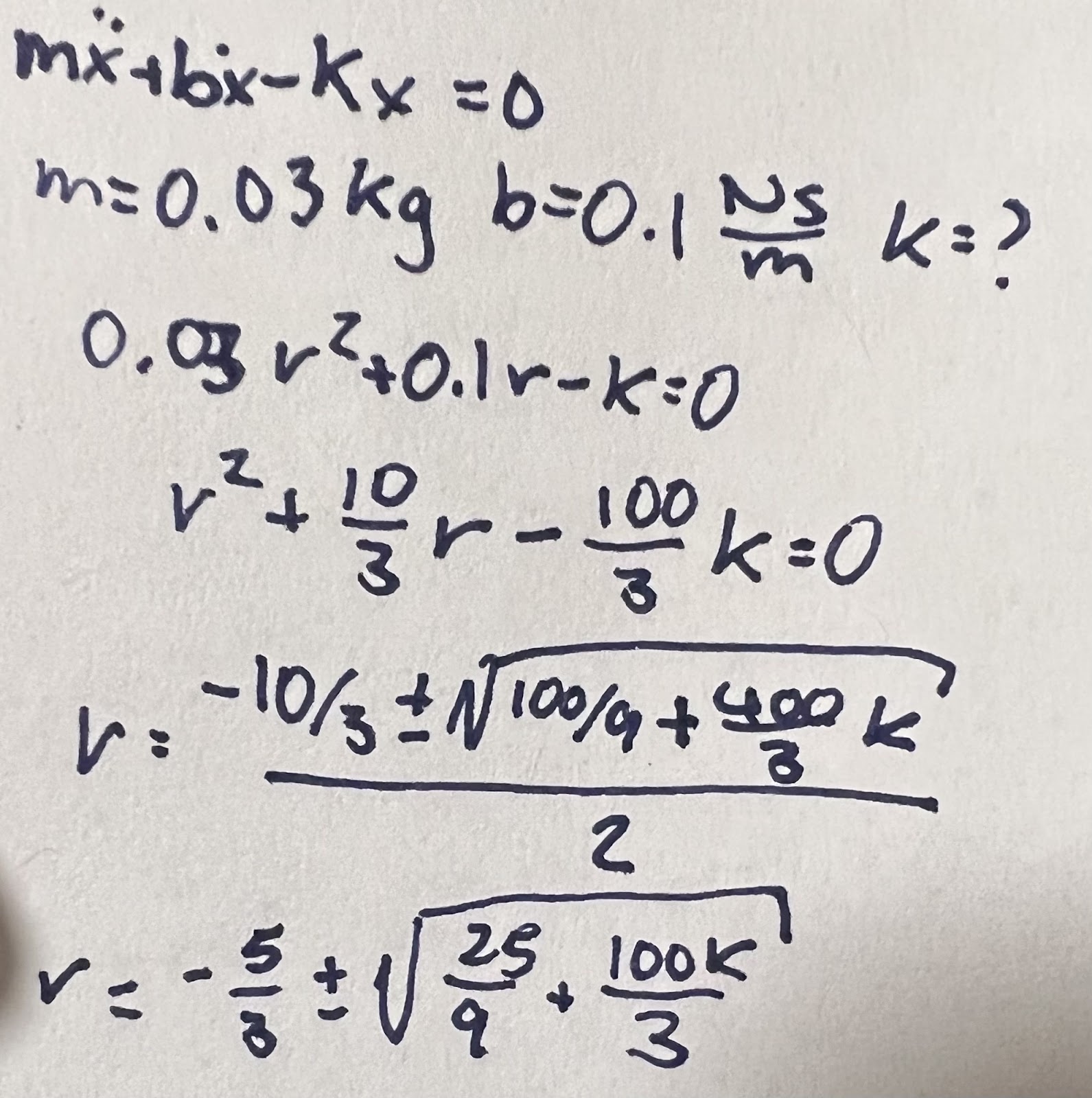
Wrote out ODE of the spring in launching action

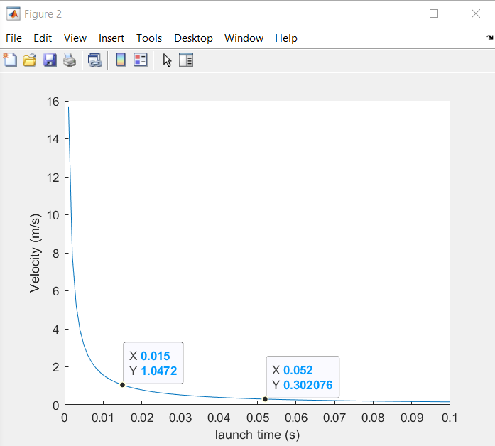
Did not solve on my calculator as the notes suggest—was giving a domain error. Instead, I solved the system on MATLAB to find the minimum spring constant with the desired velocity. 

% Lindsay Wright
% RoboSubSpring.m
% State Space for Spring and Water Damping
% Last Modified: 2/23/23

%Some assumptions: a drag coefficient of 0.01 Ns/m, pushback of 1 cm at the
%start
t=0.001:0.001:0.1;
kPlot=zeros(1,length(0.005:0.005:0.5));
vPlot=zeros(1,length(0.005:0.005:0.5));


for i=1:length(t)
    kPlot(i)=((pi/2/t(i))^2+25)/100;
    vPlot(i)=(pi/2)*0.01/t(i)*exp(-5*t(i));
end

figure
plot(t,kPlot)
xlabel('launch time (s)')
ylabel('Spring Constant (N/m)')

figure
plot(t,vPlot)
xlabel('launch time (s)')
ylabel('Velocity (m/s)')

table=zeros(3,length(t));
table(1,:)=t;
table(2,:)=kPlot;
table(3,:)=vPlot;
disp(table)

Conclusion: Need a minimum spring constant of 2750 N/m

That is a powerful spring!


Changing the distance requirement to 0.2m (about 8”) makes the needed initial velocity 2 m/s


This yields a spring constant of ~500 N/m


Changing the distance requirement to 0.3m (about 1’) makes the needed initial velocity 3 m/s

This yields a spring constant of ~1000 N/m or ~560 lbs/in


close all; clear; clc;

% Lindsay Wright

% RoboSubSpring.m

% State Space for Spring and Water Damping

% Last Modified: 2/25/23

%Some assumptions: a drag coefficient of 0.01 Ns/m, pushback of 1 cm at the

%start

t=0.001:0.001:0.1;

kPlot=zeros(1,length(0.005:0.005:0.5));

vPlot=zeros(1,length(0.005:0.005:0.5));

for i=1:length(t)

   kPlot(i)=((pi/2/t(i))^2+25)/100;

   vPlot(i)=(pi/2)*0.03/t(i)*exp(-5*t(i)); %changed 0.01 kg to 0.03 kg

end

desired_travel = 5; % in meters

diff_val = abs(desired_travel*ones(1,length(t))-vPlot);

index = find(min(diff_val) == diff_val);

%index = find(vPlot == );

figure

hold on

plot(t,kPlot)

plot(t(index),kPlot(index),'LineStyle', 'none','Marker','o','MarkerSize',5,'MarkerFaceColor','red','MarkerEdgeColor','none')

hold off

xlabel('launch time (s)')

ylabel('Spring Constant (N/m)')

figure

hold on

plot(t,vPlot)

plot(t(index),vPlot(index),'LineStyle', 'none','Marker','o','MarkerSize',5,'MarkerFaceColor','red','MarkerEdgeColor','none')

hold off

xlabel('launch time (s)')

ylabel('Velocity (m/s)')

table=zeros(3,length(t));

table(1,:)=t;

table(2,:)=kPlot;

table(3,:)=vPlot;

%disp(table)

fprintf('need: %07.4f N/m or %08.4f lb/in to travel: %07.4f meters\n',kPlot(index),kPlot(index)*8.8507457676,vPlot(index))

20230301

Calculations redone to account for differences in mass. Also realized I made an error in calculating the roots of the characteristic equation, yielding a smaller spring constant than expected.

% Lindsay Wright
% RoboSubSpring.m
% State Space for Spring and Water Damping
% Last Modified: 3/1/23
%Some assumptions: a drag coefficient of 0.01 Ns/m, pushback of 1 cm at the
%start
t=0.001:0.001:0.1;
kPlot=zeros(1,length(0.005:0.005:0.5));
vPlot=zeros(1,length(0.005:0.005:0.5));
for i=1:length(t)
  kPlot(i)=((pi/2/t(i))^2+25/9)*3/100;
  vPlot(i)=(pi/2)*0.01/t(i); %changed 0.01 kg to 0.03 kg
end
desired_travel = 0.3; % in meters
diff_val = abs(desired_travel*ones(1,length(t))-vPlot);
index = find(min(diff_val) == diff_val);
%index = find(vPlot == );
figure
hold on
plot(t,kPlot)
plot(t(index),kPlot(index),'LineStyle', 'none','Marker','o','MarkerSize',5,'MarkerFaceColor','red','MarkerEdgeColor','none')
hold off
xlabel('launch time (s)')
ylabel('Spring Constant (N/m)')
figure
hold on
plot(t,vPlot)
plot(t(index),vPlot(index),'LineStyle', 'none','Marker','o','MarkerSize',5,'MarkerFaceColor','red','MarkerEdgeColor','none')
hold off
xlabel('launch time (s)')
ylabel('Velocity (m/s)')
table=zeros(3,length(t));
table(1,:)=t;
table(2,:)=kPlot;
table(3,:)=vPlot;
%disp(table)
fprintf('need: %07.4f N/m or %08.4f lb/in to travel: %07.4f meters\n',kPlot(index),kPlot(index)*8.8507457676,vPlot(index))

Or, ~1.89 lb/in


20230508 Tuning In the O-Ring Size

  Parker handbook  4.3 Face Type Seals “Face type seals are sometimes rectangular. In designing such a seal to receive a standard O-ring, th...