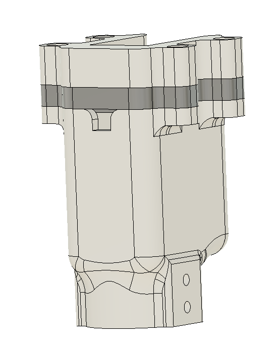
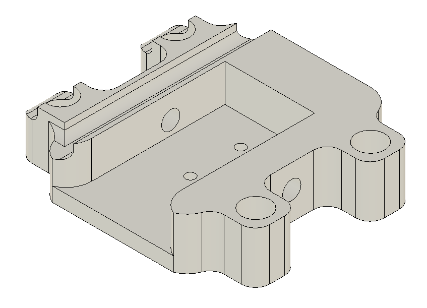
10/5/22 Altering the design to be cut by local laser cutting shop

 Colin Szeto

Lengthened the drone top plate so holes are not so close to the edge


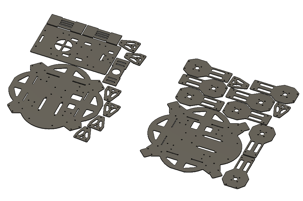
Motor mount exporting in inches


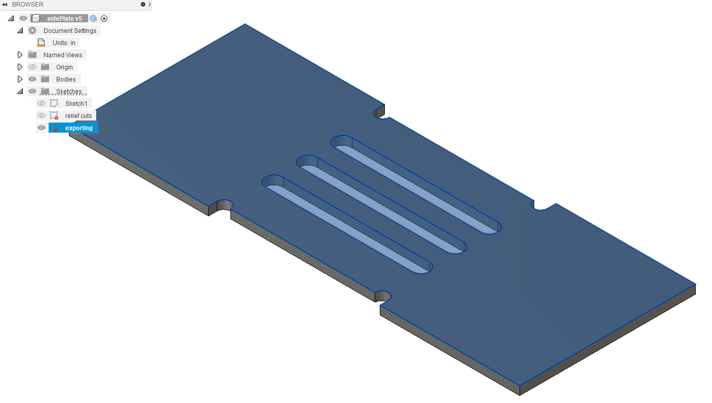
Side wall exporting in inches


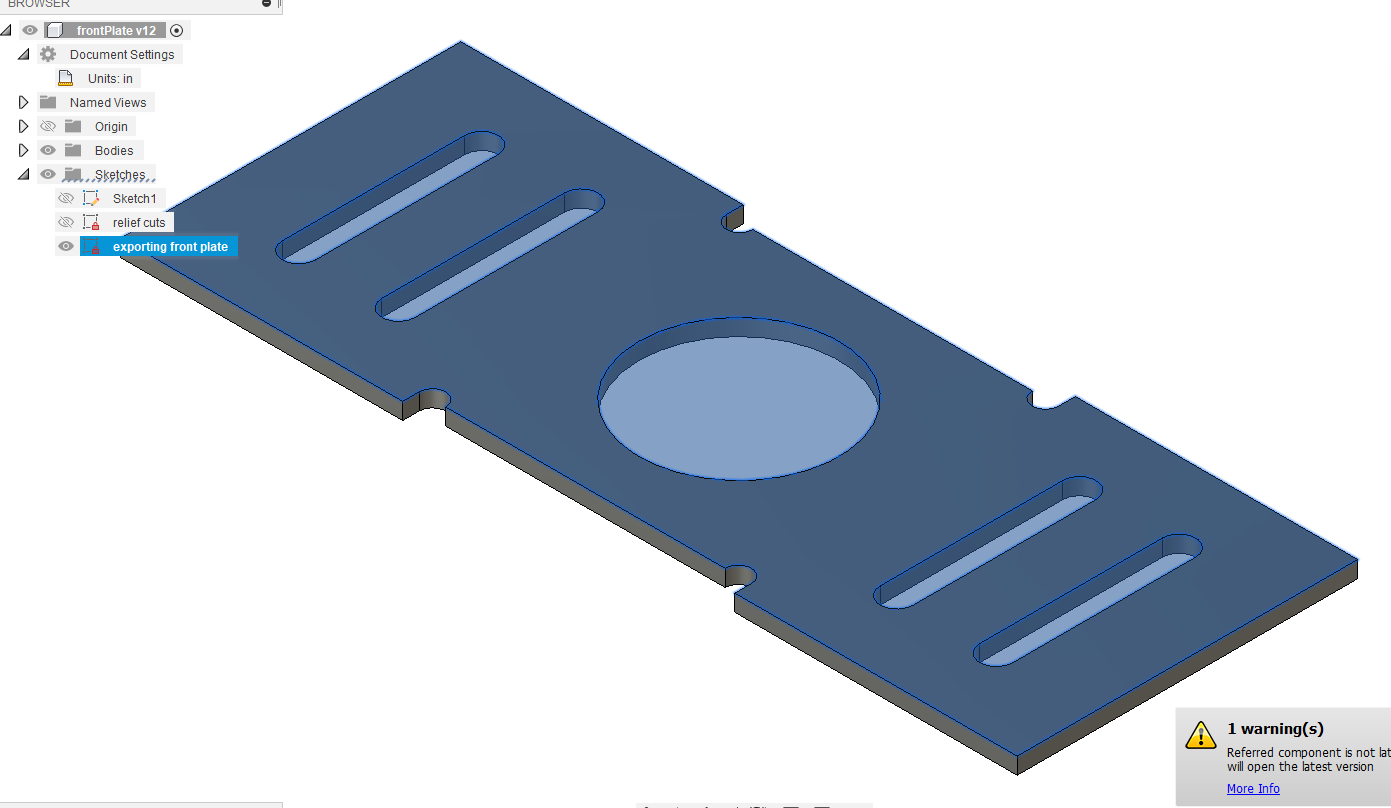
front plate exporting in inches


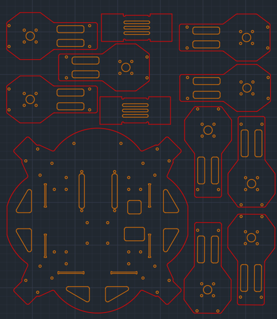
The below plates were laid out by hand 

12 motor plates

2 side walls

1 front wall

1 mid plate

1 top plate

1 bottom plate

8 leg mounting plates


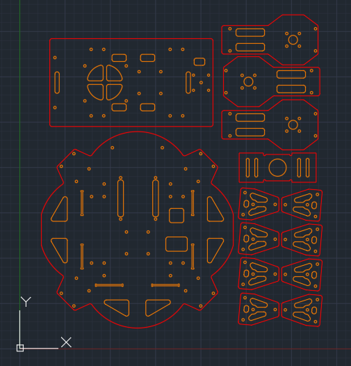
Auto Layout Arrange (Fusion 360 Feature)

Utilizing this tutorial to auto layout the parts with the correct spacing and edges


Basic steps


Preferences > Preview features > manufacturing workspace > 3D arrange

Enable Nesting trial


  1. Import components into file

  2. Create manufacturing workspace (blue means within manufacturing workspace)

  3. Right click create manufacturing model 

  4. Right click edit manufacturing model to enter into the workspace

  5. Create new component with the workspace as the parent

    1. Under each component create a sketch 

  6. Arrange, select all parts and select the sketch

  7. For the parts left over select and arrange on second sketch

  8. Create sketch, project all needed geometries into sketch (different that the intal component sketch)

  9. Export sketch

9/16/22 Using Technical Drawing References

Colin Szeto


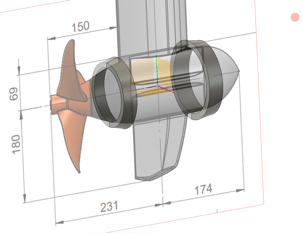
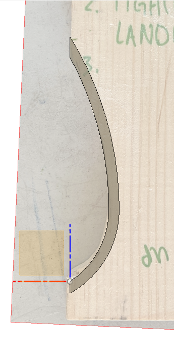
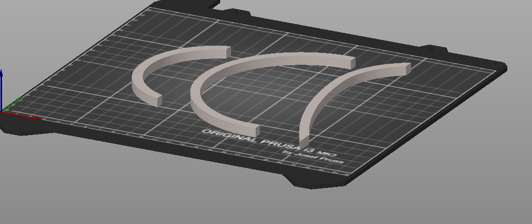
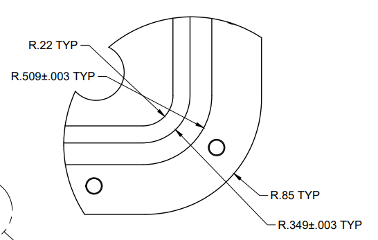
Attempting to create the ring clamps through scaling the technical drawing 1:1 scale in CAD. Utilized revolve functionality. 

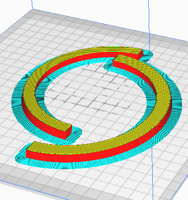
Printed out test clamps to verify geometries


9/15/22 Drone Legs and Mag Gripper Edits

Colin Szeto

Finished standing down clean the 19cm legs


Current leg options

For each of the leg options the magnetic gripper is a bit too high off the ground.

Adding in 10 mm spacer to lower the claw lower to the ground


Before


After


9/15/22 - 9/16/22 Cardboard Aided Design

 Colin Szeto


Measuring the dimensions of the Torqeedo motors utilizing cardboard templates


Originally cardboard was utilized to figure out the curvatures of the Torqeedo motors. 


Each cutout was used to progressively refine the shape

The cardboard geometry was then refined and transferred onto a wooden board. This was to allow for fine tuning the geometry of the shape with a dremel. 


The added benefit of creating the templates out of wood is that it can retain its shape better than cardboard

Transferring the carved out jigs into CAD

Printing out test parts to test the accuracy of the jigs’ measurements 


9/13/22 Gimbal CAD


Colin Szeto


Inspiration for the Gimbal here

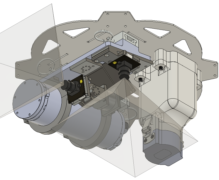
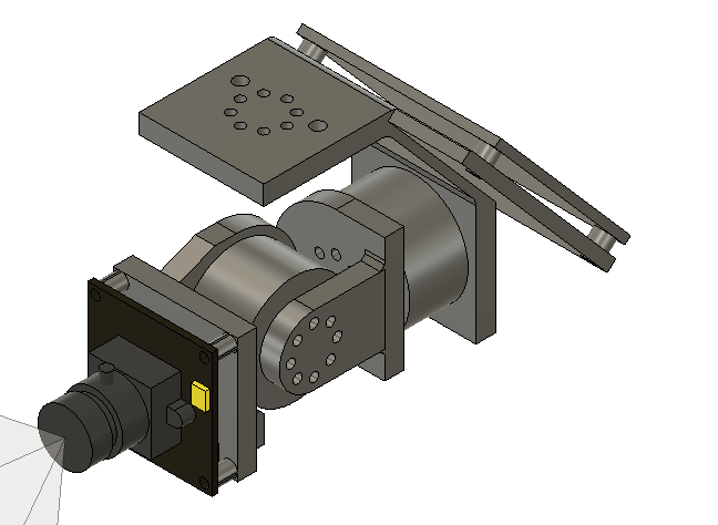
Edited the forward facing camera to be gimbaled


Edited the downward facing camera mount to interface with the low light camera


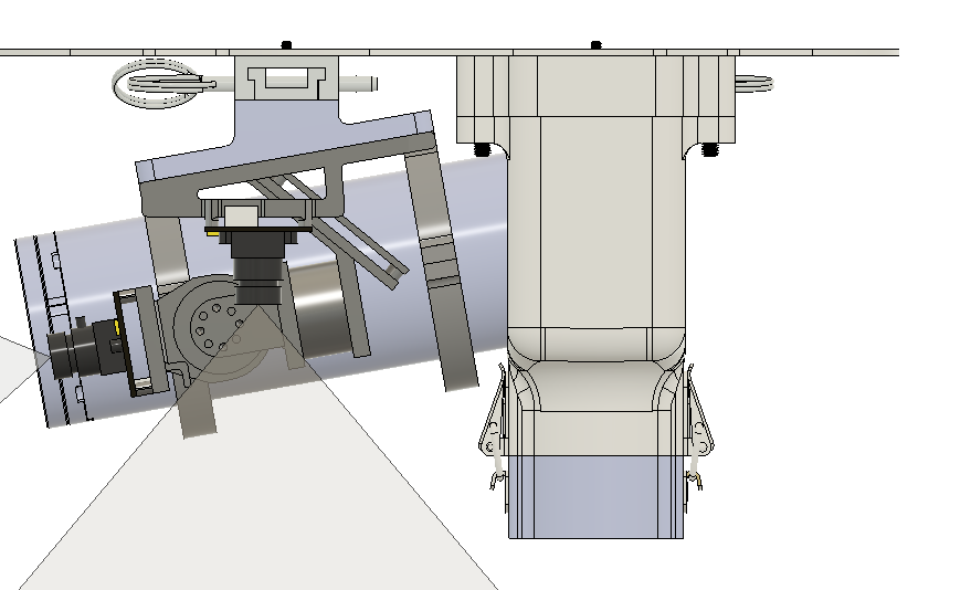
Side view of the FOV of the downward facing camera


Back view of the downward facing Camera FOV


9/11/22 Risk Reduction

Colin Szeto

Objective was to verify the feasibility of the assembly and dimensions of the motor guard around the

physical motor before laser cutting more expensive material. With no easy access to a laser cutter,

representations of the different motor guard components were laid out in 8.5 by 11 sectors to be printed

out and stitched together for 1:1 scale templates. These templates were used to guide cutting out

the designs from foam core material.
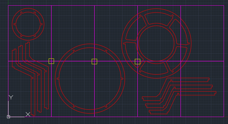

This layout of the motor guard components was created in AutoCad. The red line represented the

outline of the parts to be cut, the purple lines represented the edges of the paper, the yellow boxes

were for page alignment. The team was unable to print out each section individually. 
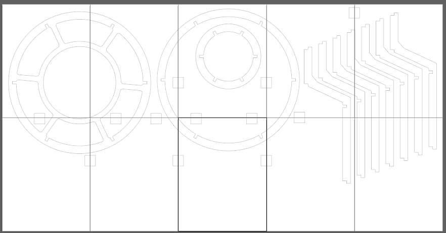

The layout of the parts was replicated in Adobe Illustrator. Artboards were placed next to one another.

This enabled splitting the design to be printed out on 8.5 by 11 sheets of paper.
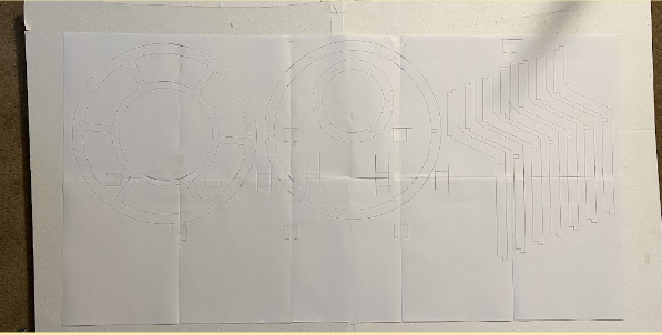


8.5 by 11 pieces of paper taped together


The foam core was roughed out to the general dimensions of the design to enable multiple people

working in parallel. 


Zoomed into the capping ring. 
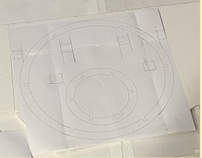


Zoomed into the intermediate ring.


In this template there are 6 pieces of paper stitched together. The template began to fall apart when we

started to cut away the material. 


For circular designs we will need to center the circles on the intersection of 4 pieces of paper.

This reduces amount of joints of paper and provides a more robust template to cut around


The negative space of the parts that were not required to be kept were darkened. This communicated

essential features versus alignment features of the individual pieces of paper


Here was all the material that needed to be removed to hit the desired geometries


Here was the final installation of the risk reduction model onto the motor
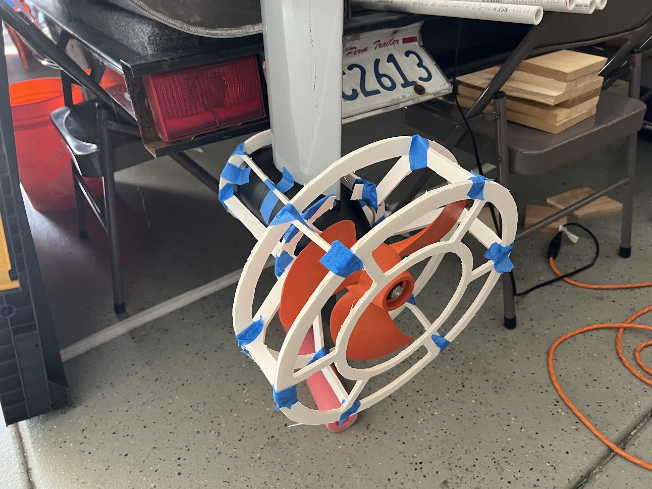


Isometric view of the foamcore motor guard


Lessons learned from the risk reduction:


  1. The motor geometry is curved, this caused deflection in material

  2. The small inner ring was unable to be installed in one piece. Current installation required the inner ring to be cut into two pieces to be installed into the assembly

  3. The two smaller ring distance needed to be shorted to reduce the forward and backwards slop due to the vertical airfoil not adequately supported
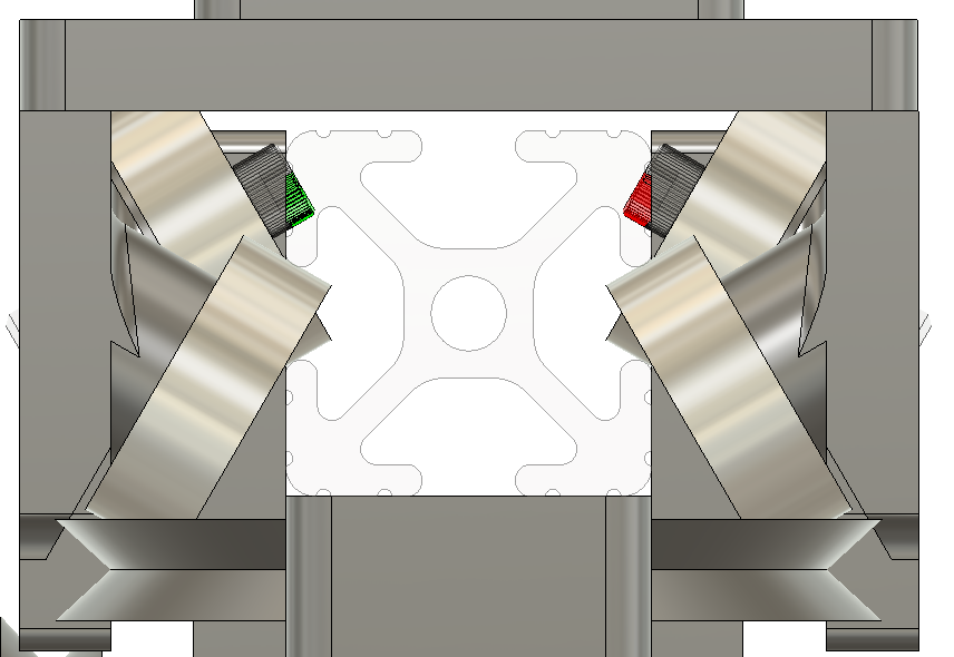
9/9/22 Reinforcing the vectored bearing holders


Colin Szeto

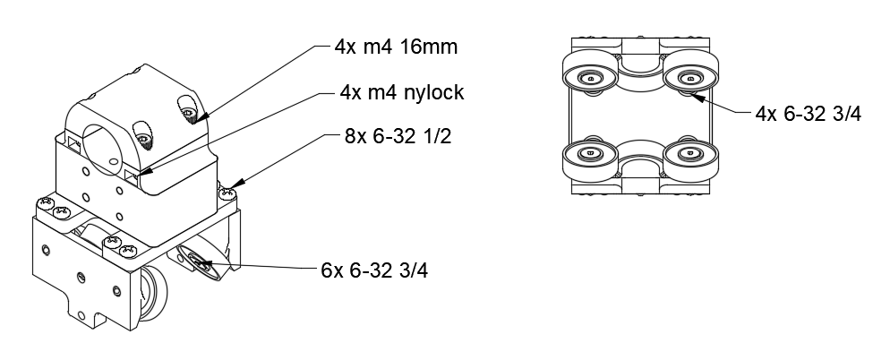
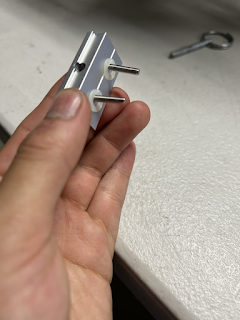
The 7mm stub broke off, there was an attempt in utilizing a 6-32 ⅞ socket head screw. This was broken when the drone platform was being stowed in between the pontoons and the cart stuck the top platform of the wam-v

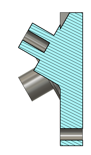
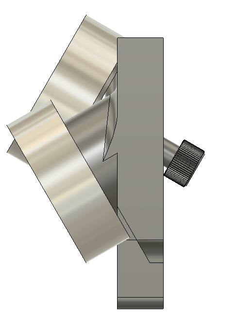
Side view cross section 

Currently the 

Side view with the hole extended through the entire part

Able to add screw to reinforce

Button head screws will interfere with the 8020 rail that the cart slides on

Could have the screw head on the outside of the part


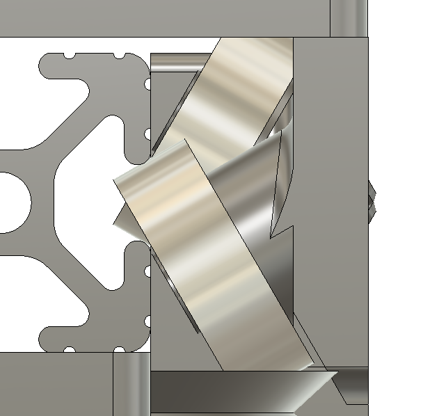
section analysis bearing holder with flat head

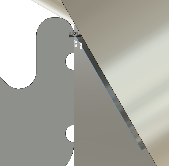
The flat heads doesn’t intersect the 8020

The clearance between the edge of the flat head and the bar is 4 thousands of an inch 

The screws used in the bearing cart (all screws multiplied by 8)


9/7/22 Attaching the Payload

Colin Szeto


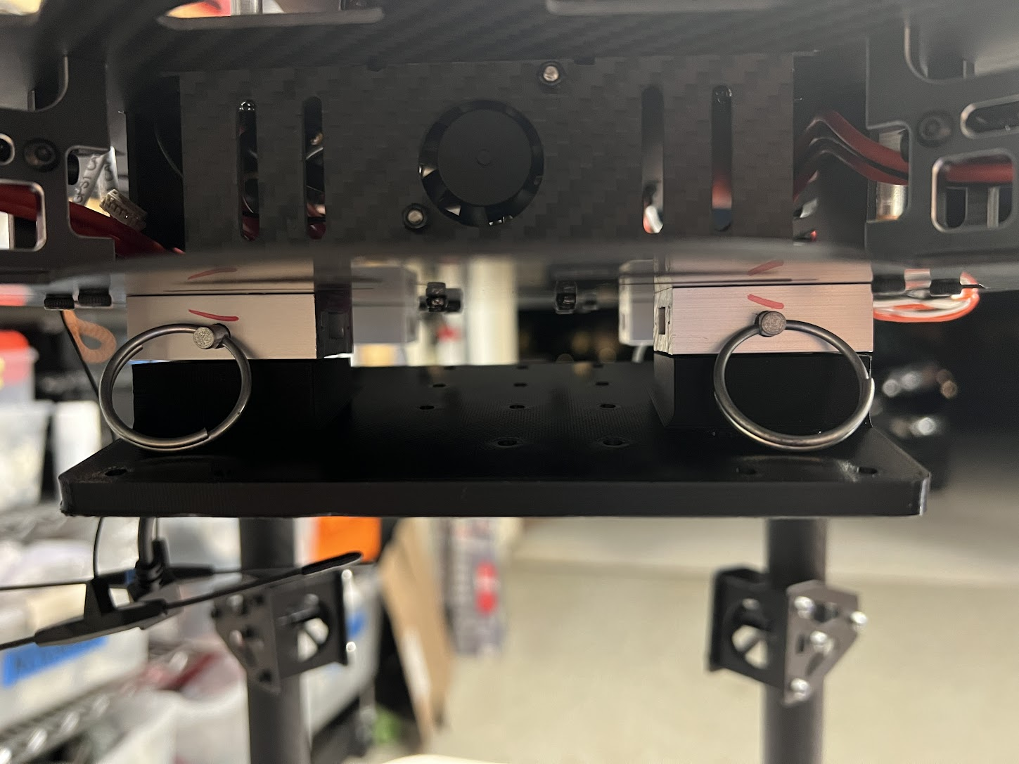
Here with the payload plate mounted onto the rail inserts the pins were not able to insert through the holes


By adding spacers between the t rail and the payload plate this eliminated the force the payload plate was pushing on the rail blocks and allowed the pin to slide through the holes easily


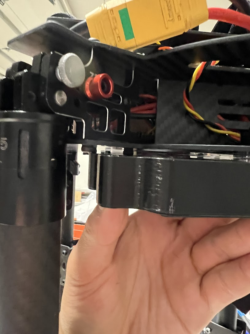
Interference was found between the magnetic claw interface plate and the mourning rail. This was due to the socket head m3 screws not modeled into the drone CAD


The drone causes quite a bit of down draft, in testing environments we want to eliminate debri jumping from the ground and cracking the oak-d lite glass lense. 


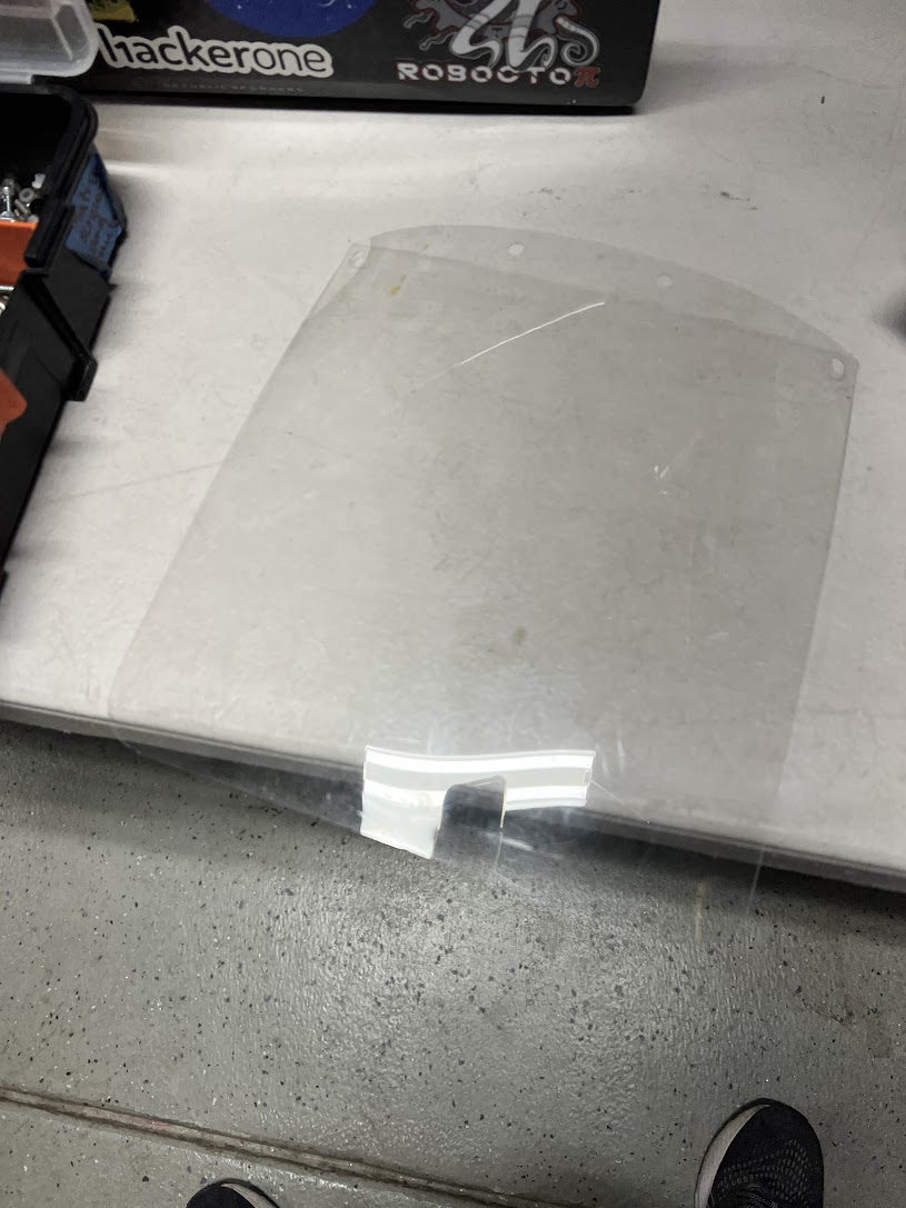
We repurposed plastic sheets used for face shield as the camera cover

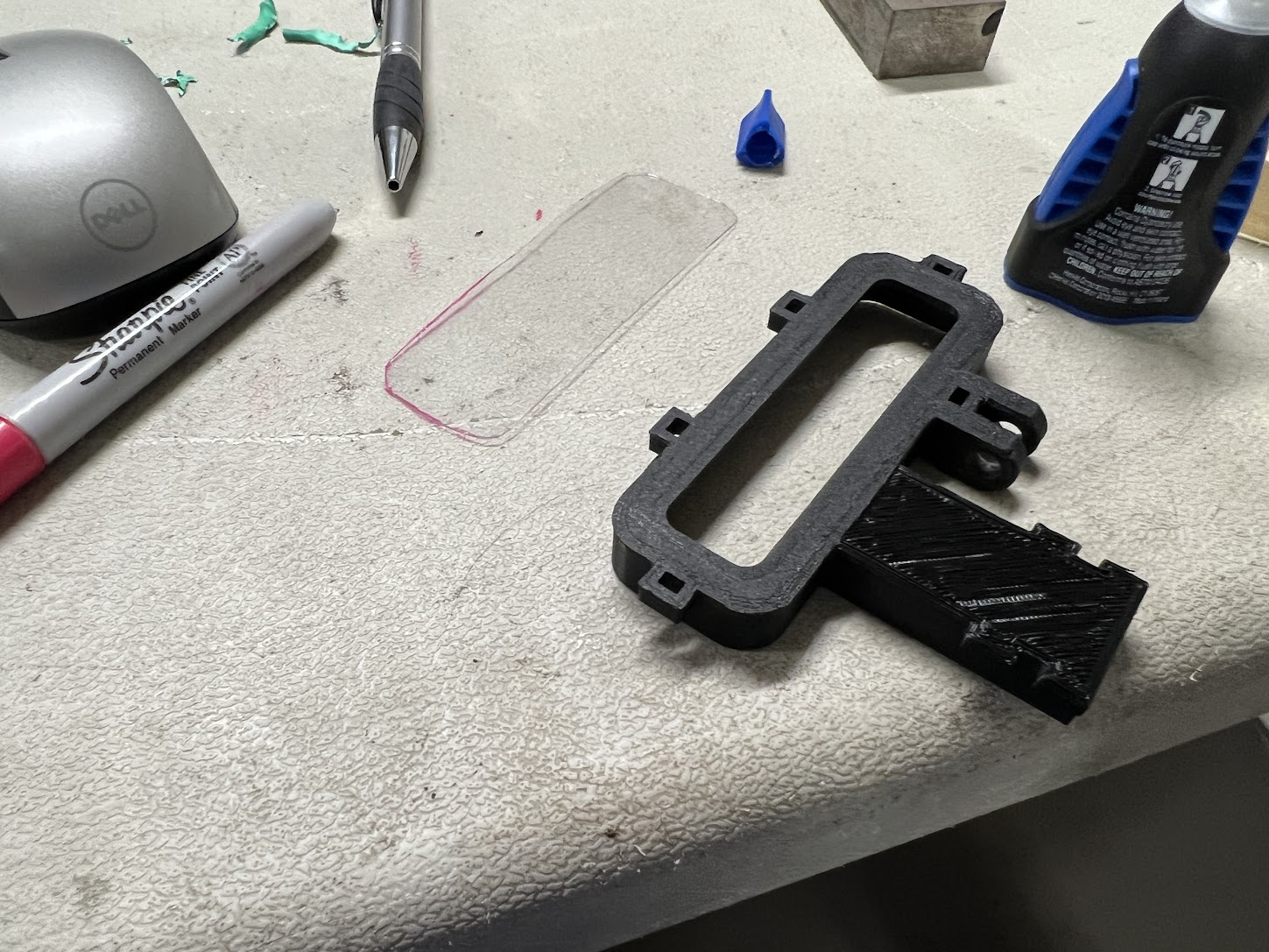
The plastic was cut to size to be glued onto the oak-d lite camera holder


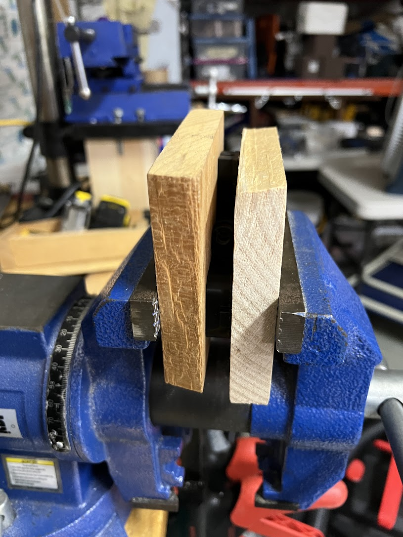
The glue up was transferred to the vice to apply even constant pressure along the mated faces


This is the final result with the plastic adhered onto the front of the oak-d lite case


Here is both the HSI camera and the bottom facing oak-d lite mounted onto the payload rail mounted on the drone


9/7/22 Building drone landing platform

20230508 Tuning In the O-Ring Size

  Parker handbook  4.3 Face Type Seals “Face type seals are sometimes rectangular. In designing such a seal to receive a standard O-ring, th...