9/1/22 Finalized version of Drone Landing Platform Structure


Colin Szeto

This section overviews the decision making on why 1020 construction was selected in creating the drone landing platform


Link to File here

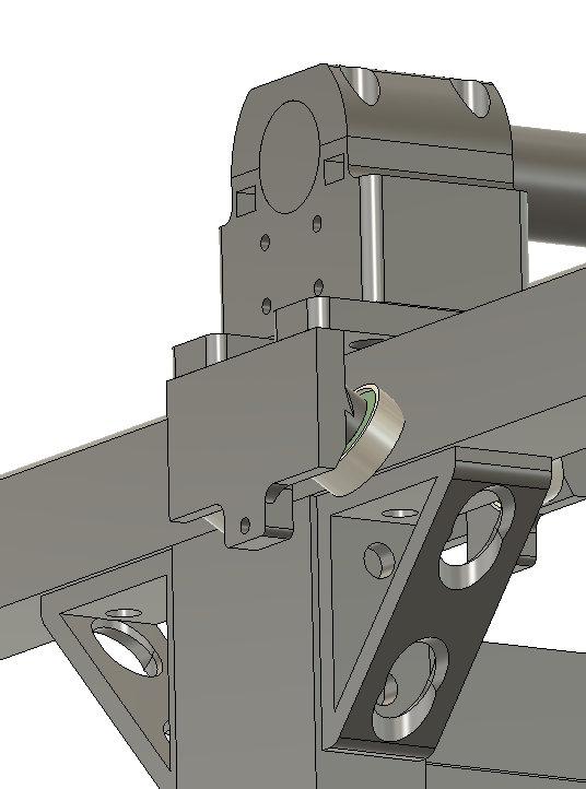
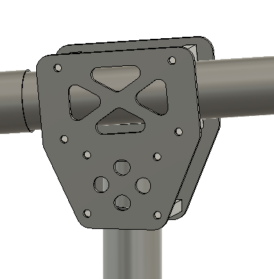
The bearings intersect with the existing solution for mounting the 8020 cross braces on the bottom of the 8020 rail
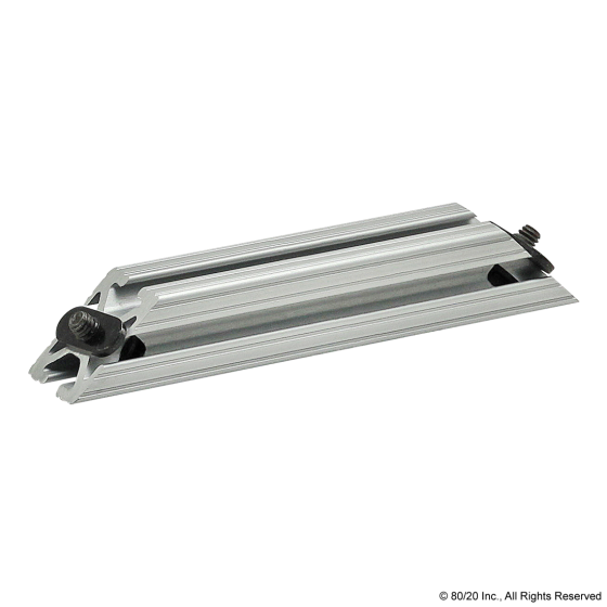
An alternative solution was to use the 8020 part number 2565


Part website here


However each of these angled profiles had a unit cost of 20 dollars. This would come up to a minimum of 160 dollars if we wanted to support the horizontal rails

An alternative solution was devised to utilize 1020 bars (1 in by 2 in) as the support
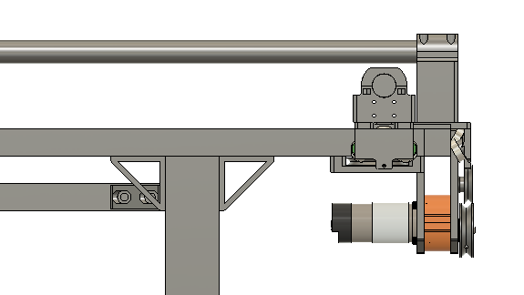
This usage of 1020 allows the carts to freely move along the bars with providing support the construction.


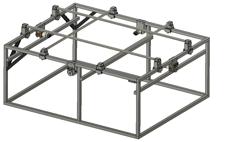
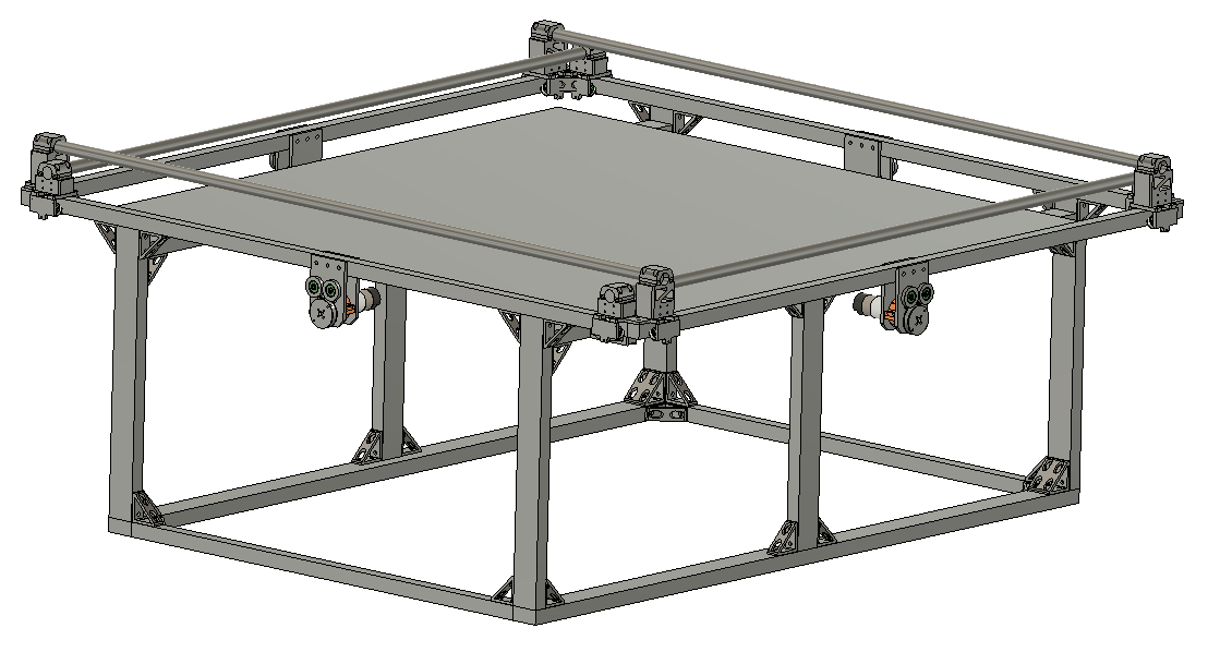
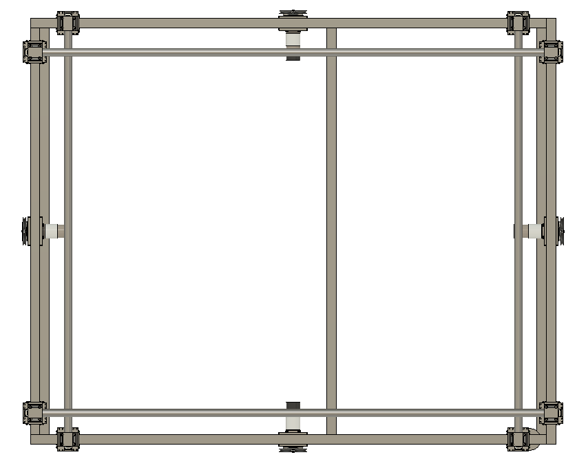
This top view illustrates the landing platform will be amply supported


This triple bar configuration would not have provided ample support for the landing platform.

Parts list and supporting documents: here
9/1/22 What About Galvanic Corrosion


Colin Szeto

Galvanic corrosion when contact with the ocean


Damon McMillan here speaks about galvanic corrosion when stainless steel is submerged with carbon fiber for a long period of time in the ocean


Video overviewing prevention methods of galvanic corrosion: here


About Galvanic Corrosion here

Ways of avoiding Galvanic Corrosion here

8/31/22 Laying out Electronics + First Two Sided Test

 Colin Szeto

Added in the battery and emo box representation onto the top of the wam-v platform


File location:

Electronics > “laying out on the top of the platform”

Construction of all 4 sides of the landing platform

The longer bars compressing 

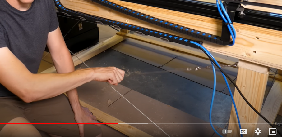
Thinking of utilizing steel cables to make a criss cross pattern to introduce rigidity to the design


Reference here

By the end of the day utilizing off cuts this was the current configuration of the drone landing platform. A solution for supporting the landing plate the drone feet will interface with has yet to be designed.


8/31/22 Fabricating and Mounting Minimized Drone landing plates


Colin Szeto

Fabricating the smaller landing plates

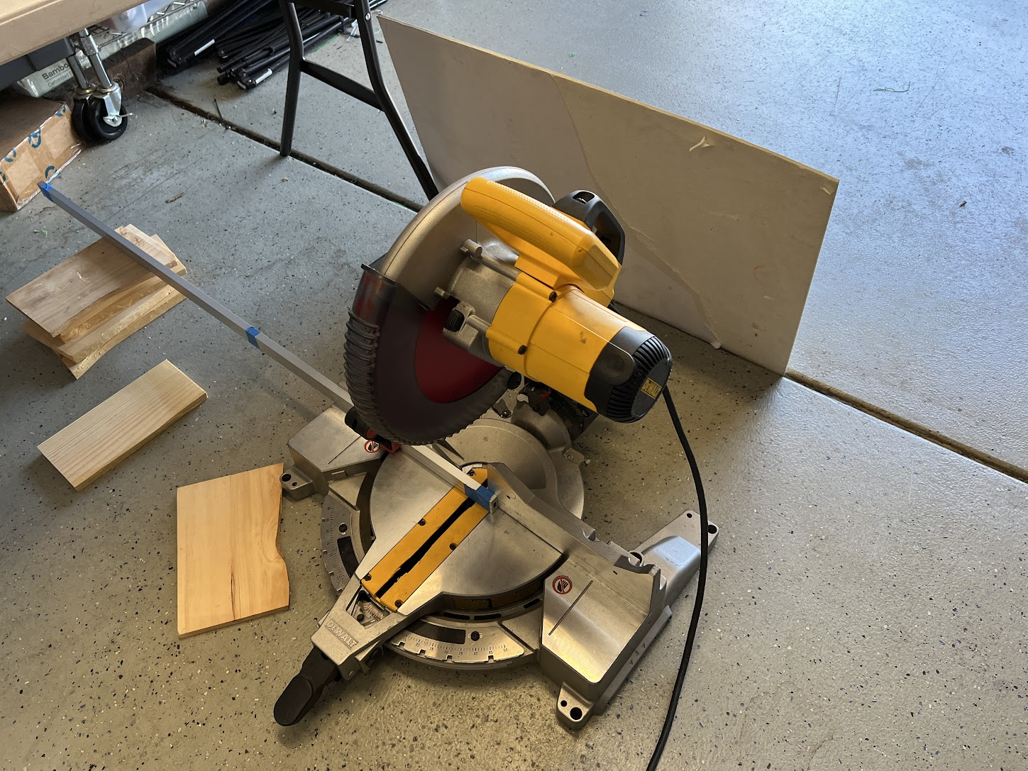
Configuration used for cutting the drone mourning rails. The rails were taped together to get a consistent cut across both pieces. A Backer was set up behind the chop saw to catch all the metal particles


Cut and drilled holes for the quick mounting blocks which integrate with the bottom drone plate

Drill bits used for fabricating the rail blocks:


3/16 for the pin hole


3 mm for the mounting holes


Able to mount the smaller profile landing plates


8/30/22 Designing Minimized Drone Landing Plates

Colin Szeto

Deemed that one clamp was enough on the motor arms. Changed the clamp location directly above the legs


8/30/22 Fabricating Drone Landing Plates and Assembly


Colin Szeto

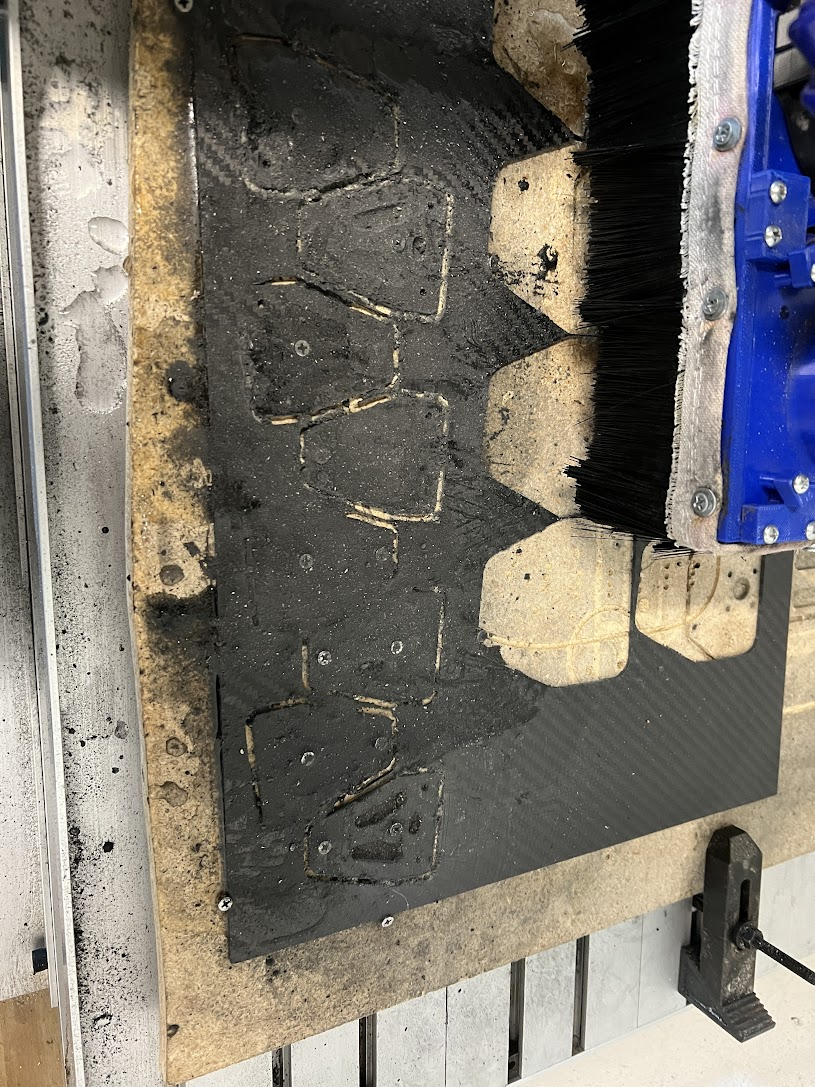
Utilized desktop cnc, did not use air compressor and water mixture, the carbon fiber dust got everywhere


Edges of the parts before wet sanding


Edges after wet sanding


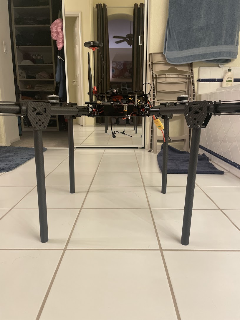
Front view of the drone landing plates connected to the legs. Utilizing 2 clamps instead of the intended 4 clamps. This decision was made as only had 8 clamps on hand. Demonstrated that landing plates only required two clamps rather than 4 as there was more than enough clamping force


8/28/22 Initial design of the Drone Landing Plate


Colin Szeto

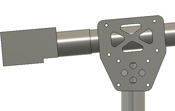
The objective is to sandwich the tube clamps between two carbon fiber plates. In this design, the vertical plates constrain 4 tube clamps together to adapt from the motor arm titled up 15 degrees from horizontal to a tube vertical to the floor.


8/27/2022 Ideating Hydrophone Boom Arm

Colin Szeto

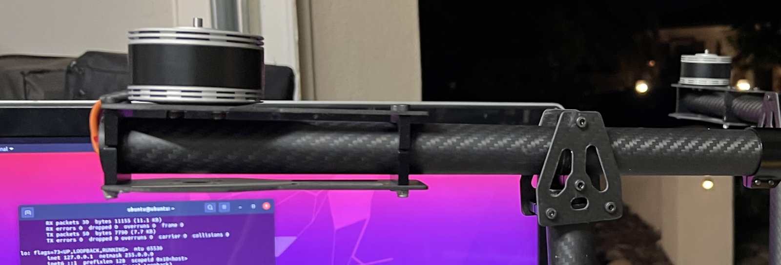
Mounting a fold down mechanism onto the existing motor holder


file location of the cad model 


Could use a rod to roll within the 80/20 profile to rotate the motor mounts

80/20 pivot solution here

8/15/22 Initial Fitment of T500 in Motor Saver + Initial Fitment of SendCutSend Parts


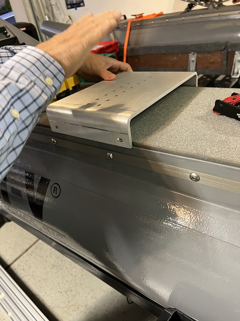
Received the SendCutSend parts - cut and bent 5052 aluminum. Pretty cool how the parts have vacuumed formed plastic on a cardboard backing

In the CAD the top of the skis where the outer plates secure the skis to the aluminum was 10.25” apart. 


On the actual WAM-V the plates are 10.5” apart. 


Lessons learned is to measure the actual WAM-V placement instead of relying on the provided WAM-V CAD

Test fitment of the T500 on the enlarged motor savers. 


The m4 screws needed to be drilled into the mounting holes to melt the plastic around the screws for final dimensions. This is done by inserting the screw through the hole and spinning the screw, the friction between the screw and the PLA forms the desired shape of the plastic around the screw. 


Alternatively, we could have used longer m4 screws but our local hardware store’s longest m4 screw length was 16mm

20230508 Tuning In the O-Ring Size

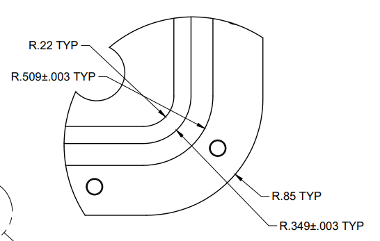
  Parker handbook  4.3 Face Type Seals “Face type seals are sometimes rectangular. In designing such a seal to receive a standard O-ring, th...