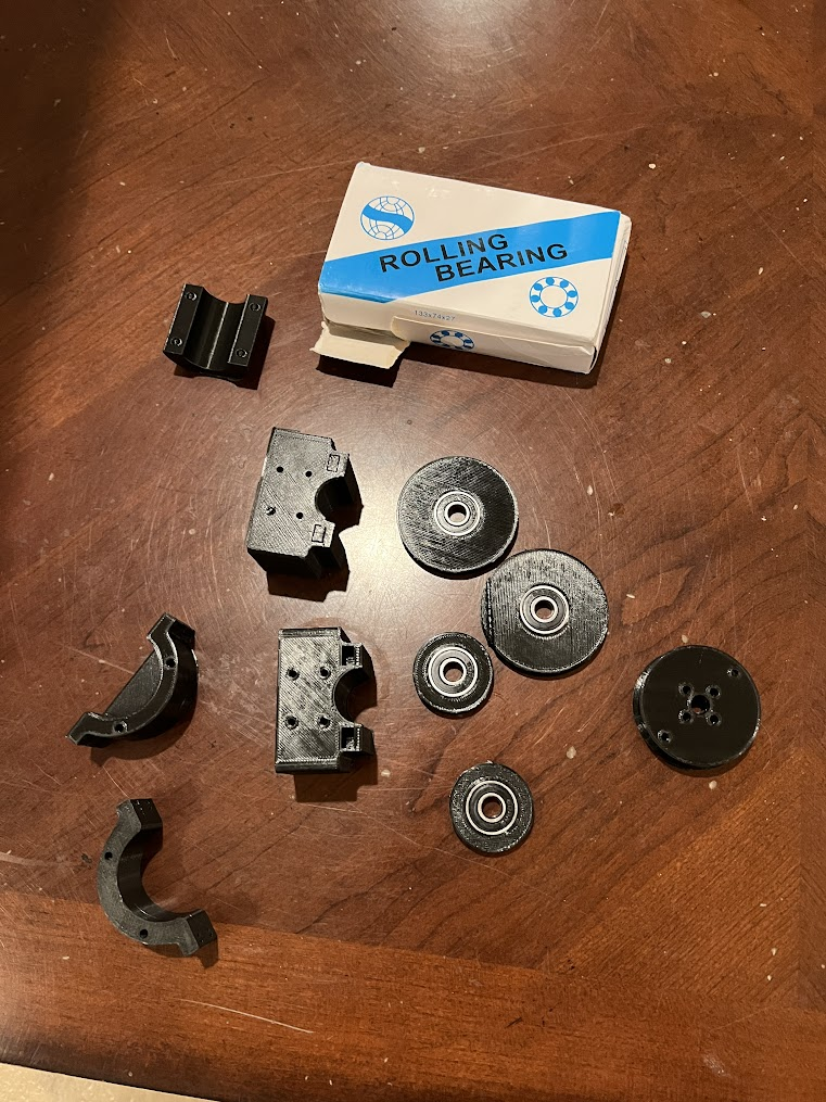
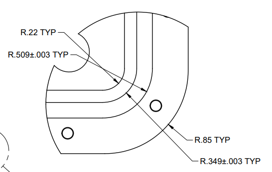
8/28/22 Initial design of the Drone Landing Plate


Colin Szeto

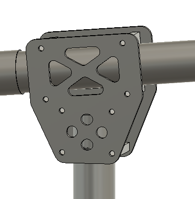
The objective is to sandwich the tube clamps between two carbon fiber plates. In this design, the vertical plates constrain 4 tube clamps together to adapt from the motor arm titled up 15 degrees from horizontal to a tube vertical to the floor.


8/27/2022 Ideating Hydrophone Boom Arm

Colin Szeto

Mounting a fold down mechanism onto the existing motor holder


file location of the cad model 


Could use a rod to roll within the 80/20 profile to rotate the motor mounts

80/20 pivot solution here

8/15/22 Initial Fitment of T500 in Motor Saver + Initial Fitment of SendCutSend Parts


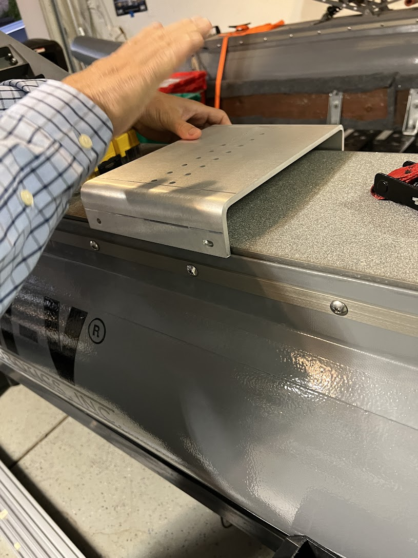
Received the SendCutSend parts - cut and bent 5052 aluminum. Pretty cool how the parts have vacuumed formed plastic on a cardboard backing

In the CAD the top of the skis where the outer plates secure the skis to the aluminum was 10.25” apart. 


On the actual WAM-V the plates are 10.5” apart. 


Lessons learned is to measure the actual WAM-V placement instead of relying on the provided WAM-V CAD

Test fitment of the T500 on the enlarged motor savers. 


The m4 screws needed to be drilled into the mounting holes to melt the plastic around the screws for final dimensions. This is done by inserting the screw through the hole and spinning the screw, the friction between the screw and the PLA forms the desired shape of the plastic around the screw. 


Alternatively, we could have used longer m4 screws but our local hardware store’s longest m4 screw length was 16mm

8/15/22 Assembly and First Test of Drone Landing Platform Single side

 Colin Szeto

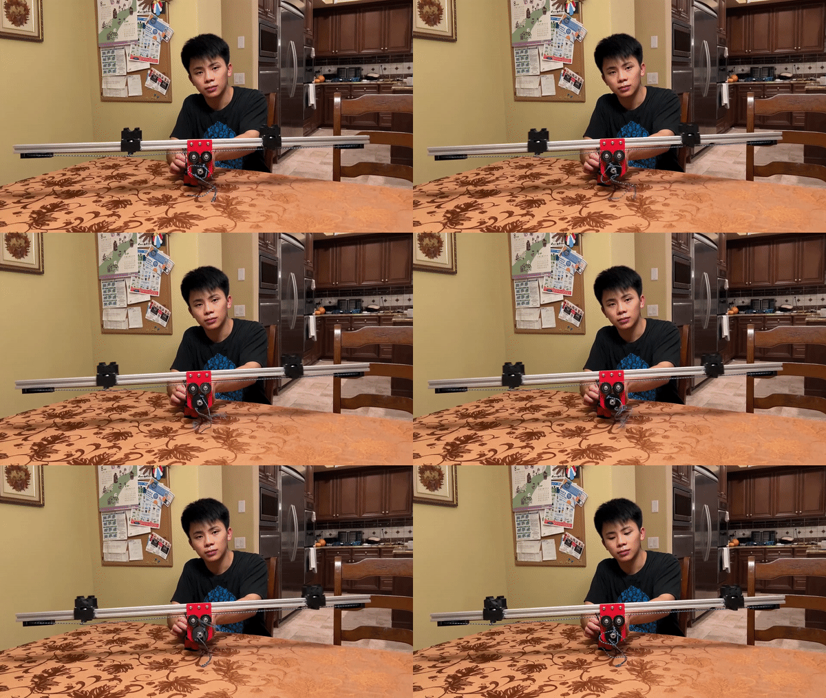
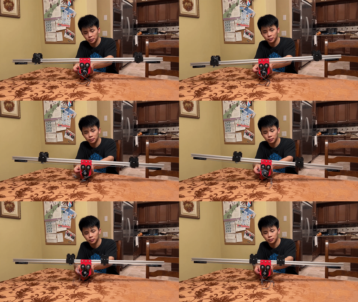
Opening of the carts

When the motor is reversed the carts roll towards the center of the bar


8/14/22 Fabricating Drone Landing Platform

Colin Szeto

The parts were printed in black PLA as that is what was available at the moment.

This is a gash on one of the 3d printed parts as the preheated hot end dragged through the completed spool. This was due to the 3d printed spool jamming and the print continued without extruding filament.


Reference on how to save 3d prints here


The print height was measured at the spool height, as the hot end was moving to other parts on the print bed the nozzle grazed through the spool. After recollecting the correct height the print failed and the print was able to be resumed.


8/13/22 Building the Motorized platform v2

 Colin Szeto

The objective here is to utilize the vectored bearing design first implemented in the HSI testing rig. This allows the elimination of the friction fully 3d printed spools.

To the left we have the vertical spools. This allows for packaging as well as aligns all of the spools.


Note the green line represents the path of the string 

8/13/22 Dimensioning out the Shipping Crate

Colin Szeto

Plywood is good enough for the competition. We can consider purchasing the plywood at Australia

Outer dimensions of the box

Length – 123” (3.1242 meters)

Width – 54” (1.3716 meters)

Height – 62” (1.5748 meters)
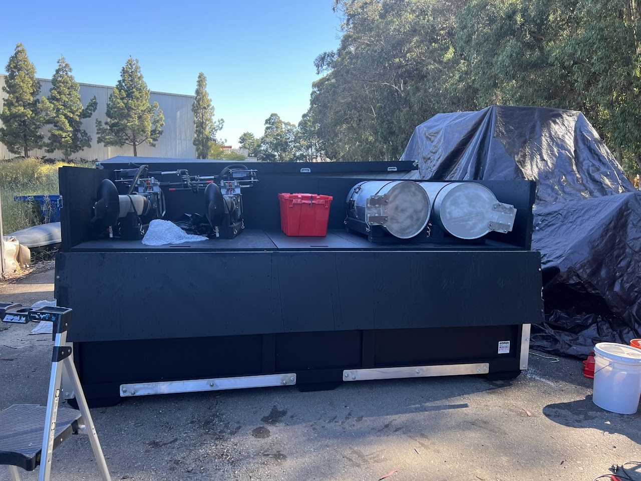
Here is an example of the crate with the motor holders as well as the pontoons of the upper portion of the shipping box
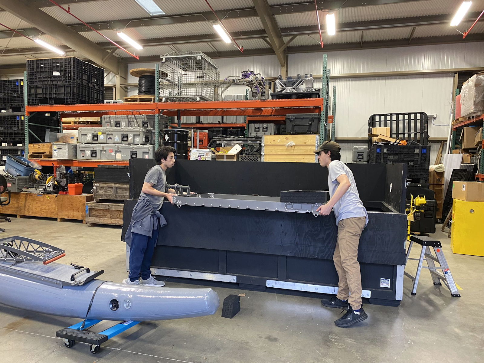
The box has a top and a bottom, here are two students lifting out the top platform of the WAM-V from the lower position of the box


here  is reference for the above photo

This is a possible placement on top of the skis


This volume on the skis 33 in by 6 in by 48 in 

Teal and yellow: pontoons 

salmon pink and orange: area for the drone platform 

Green: thruster location


(height, width, depth)

Orange dimensions: ~6 in 33in ~48in

salmon pink dimensions: ~17 in ~28in ~48 in 
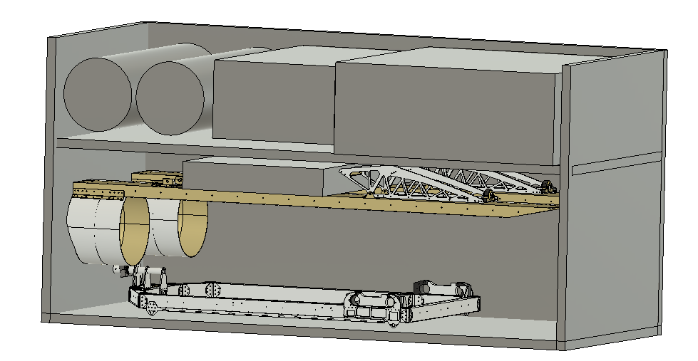

Rough dimensions of the wam-v shipping container with the 

20230508 Tuning In the O-Ring Size

  Parker handbook  4.3 Face Type Seals “Face type seals are sometimes rectangular. In designing such a seal to receive a standard O-ring, th...