Colin Szeto
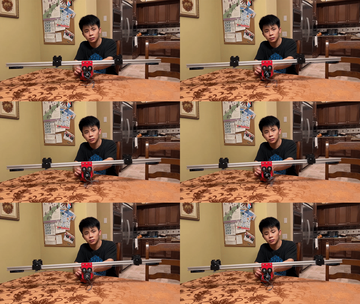
Opening of the carts
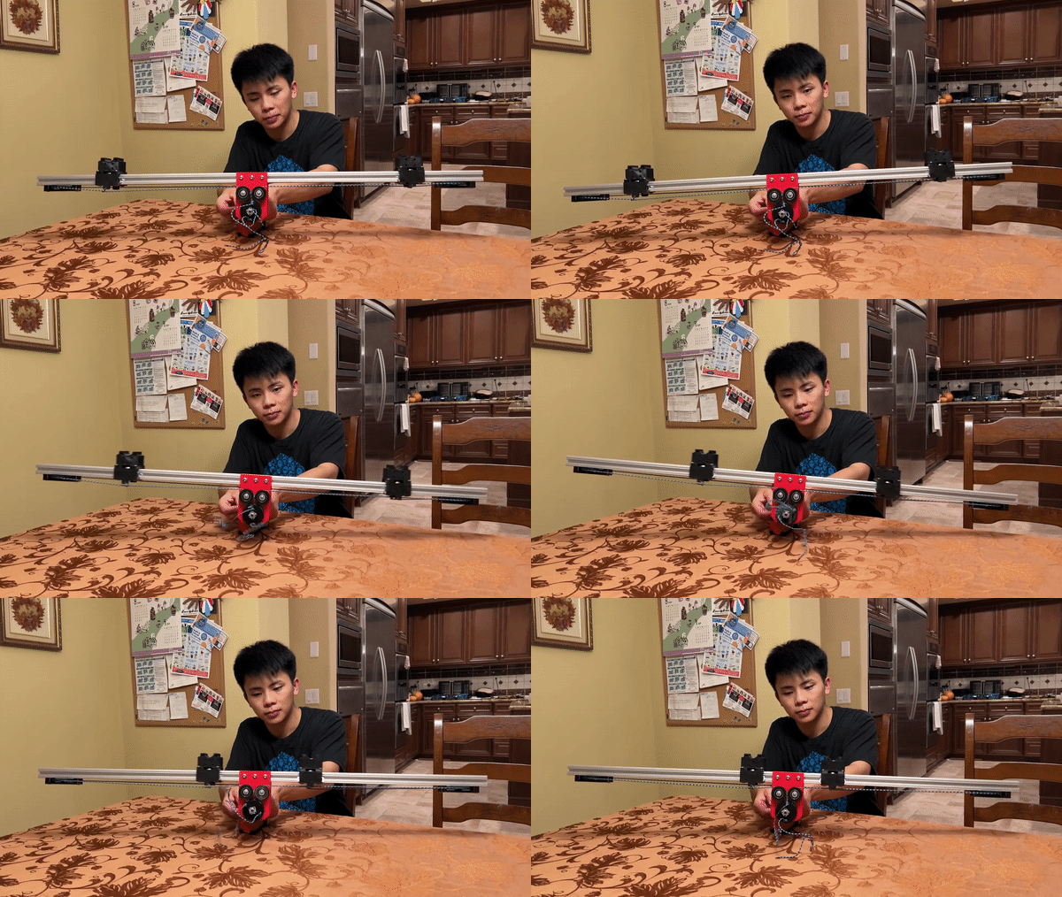
When the motor is reversed the carts roll towards the center of the bar
Colin Szeto
Opening of the carts
When the motor is reversed the carts roll towards the center of the bar
Colin Szeto
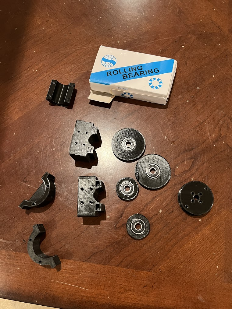
The parts were printed in black PLA as that is what was available at the moment.
This is a gash on one of the 3d printed parts as the preheated hot end dragged through the completed spool. This was due to the 3d printed spool jamming and the print continued without extruding filament.
Reference on how to save 3d prints here
The print height was measured at the spool height, as the hot end was moving to other parts on the print bed the nozzle grazed through the spool. After recollecting the correct height the print failed and the print was able to be resumed.
Colin Szeto
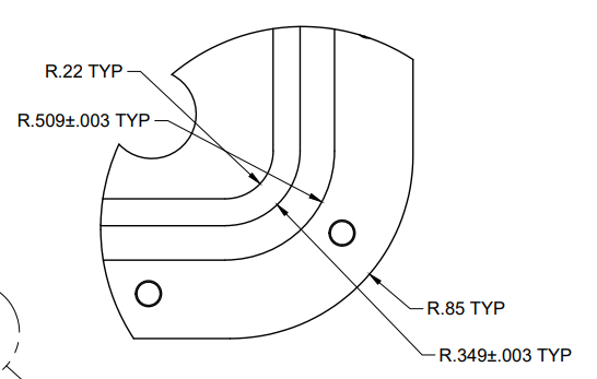
The objective here is to utilize the vectored bearing design first implemented in the HSI testing rig. This allows the elimination of the friction fully 3d printed spools.
To the left we have the vertical spools. This allows for packaging as well as aligns all of the spools.
Colin Szeto
Plywood is good enough for the competition. We can consider purchasing the plywood at Australia
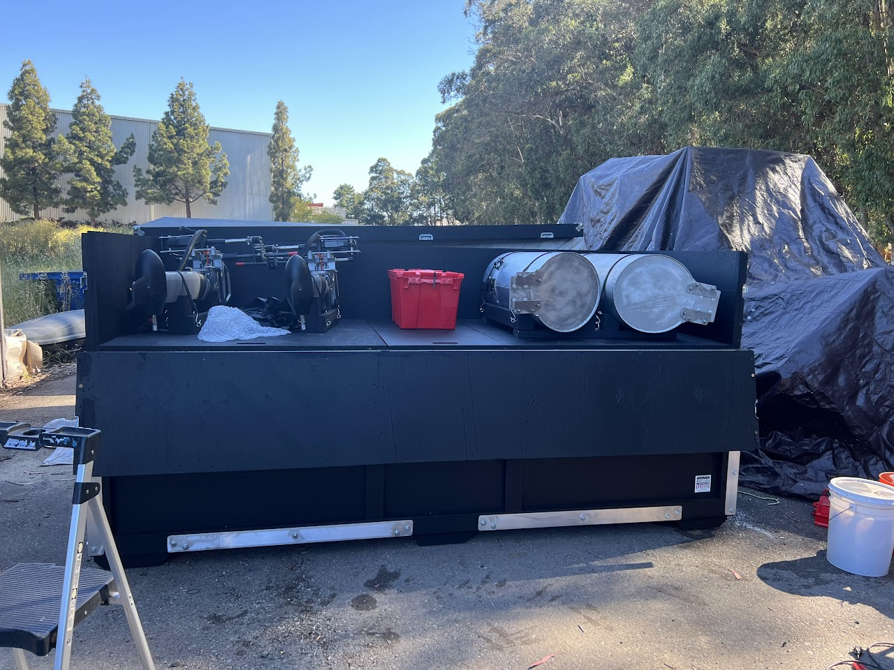
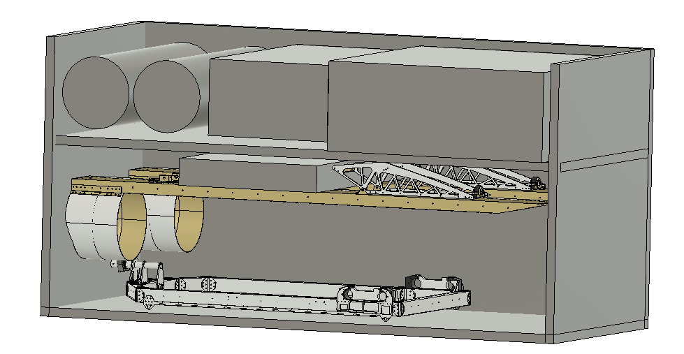
Outer dimensions of the box
Length – 123” (3.1242 meters)
Width – 54” (1.3716 meters)
Height – 62” (1.5748 meters)
Here is an example of the crate with the motor holders as well as the pontoons of the upper portion of the shipping box
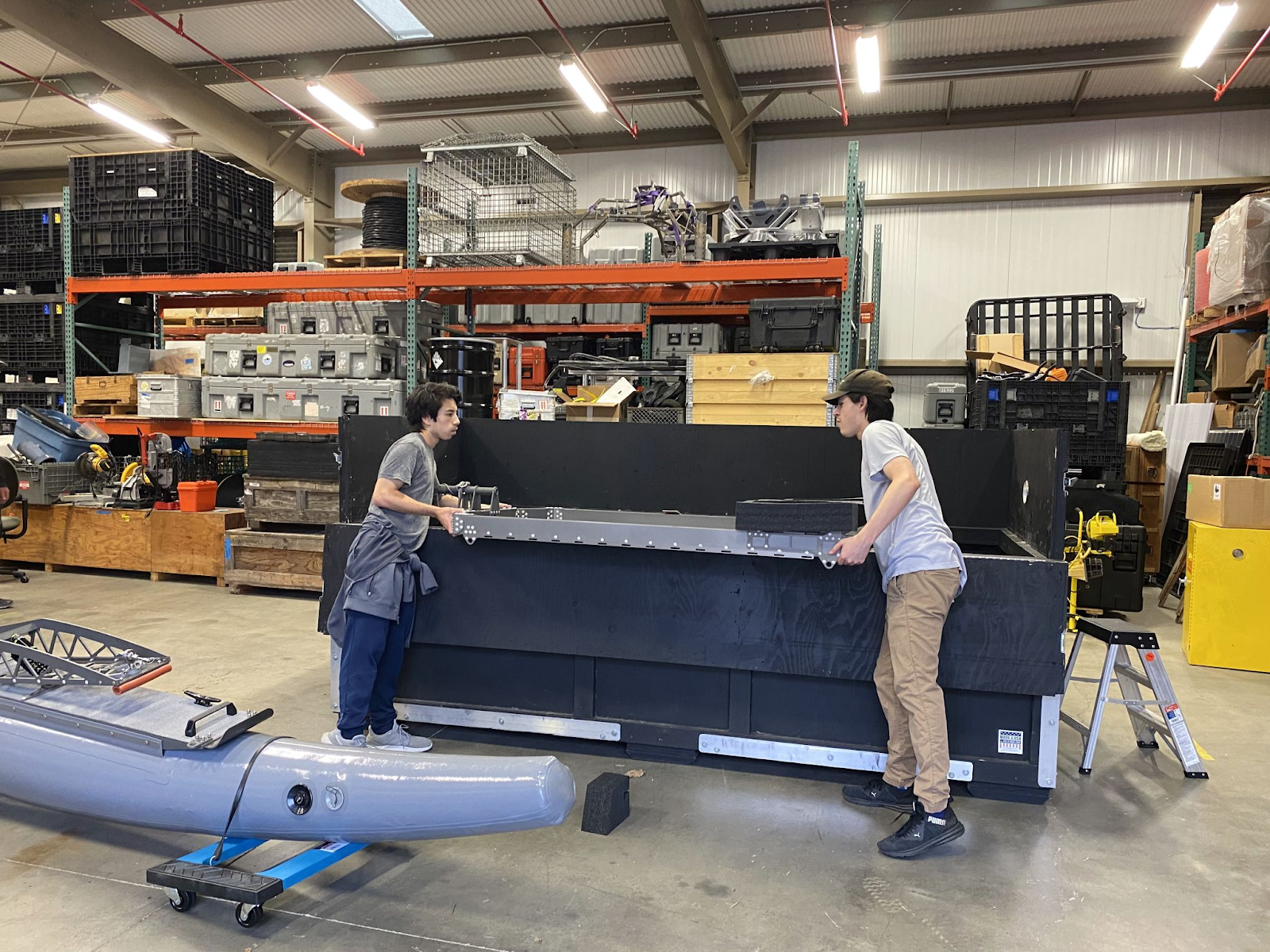
The box has a top and a bottom, here are two students lifting out the top platform of the WAM-V from the lower position of the box
here is reference for the above photo
This is a possible placement on top of the skis
This volume on the skis 33 in by 6 in by 48 in
Teal and yellow: pontoons
salmon pink and orange: area for the drone platform
Green: thruster location
(height, width, depth)
Orange dimensions: ~6 in 33in ~48in
salmon pink dimensions: ~17 in ~28in ~48 in
Rough dimensions of the wam-v shipping container with the
Colin Szeto
The aluminum interface plate was duplicated 3 more times for all of the legs of the prototype boat
Colin Szeto
It was only a matter of time when the acrylic interface plates were dropped on the floor and snapped
The team pivoted to utilize the aluminum 6061 plates we had on hand.
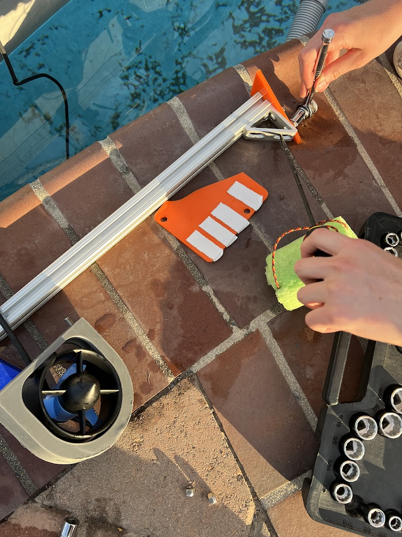
The hole pattern was printed on 1:1 scale onto an 8.5” by 11” piece of paper. The design was then cut out and attached to the plate. This allowed the team to center punch accurately and maintain tolerances with only a drill press
Hello coach Alex and everyone,
I wanted to give you all a quick little update on where things are at with the manipulator system. There are pictures attached so you have an idea of what I am working on.
Basically, the manipulator system will utilize this mechanical magnet called a mag-switch which essentially turns the magnet off and on at a turn of a knob (video of it in use attached). The system will use the servo to turn this knob.
I am currently designing the mount for the system which will hold the servo and the knob together on the drone. I have finished the lower part that will hold the mag-switch in an easy-to-remove section that will be held by two latches so that the mag-switch can be easily removed and cleaned to prevent any rusting that could possibly happen after use. I am currently in the process of designing the main top body of the manipulator which will house the servo and a downward-facing camera and will attach to the drone mounts.
Speaking of the drone mounts, I have created a redesign of the mounting system for the drone which will use rails and pins to hold the camera and manipulator closer to the main body, this should help its maneuverability in the air. However, having made this change using the holes already on the frame the camera will sit towards the front of the drone rather than in the center. Hopefully, once I finish the manipulator things should balance out since it will be attached to the back two rails; but I may make some adjustments to attend to this problem.
Regarding materials, the rails will be aluminum and the manipulator will most likely be printed using ABS material (unless I find a stronger alternative). Otherwise, please let me know if you guys have any questions or thoughts on this new rail system and the manipulator system.
Also, I would like to let you guys know that I will be gone on a family camping trip starting tomorrow for a week, so I will not be able to work on this during that time but I should be able to finish things once I get back. Either way, I will still be able to answer any questions you all may have in the meantime.
Other than that, I hope all of you guys have a good weekend.
Colin Szeto
Side view 2 plates, 4 spacers
2 1020 bars
4 4138 gussets
Utilizes the same motor mounting structure for the front vectored plates
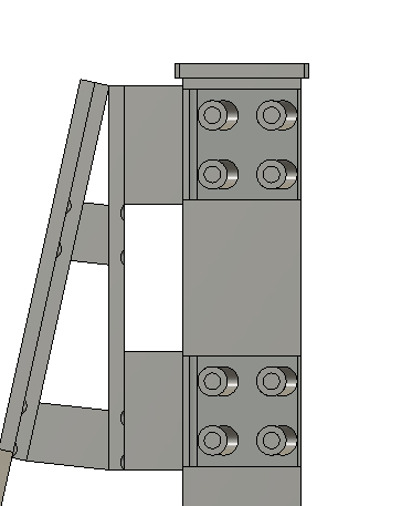
Notice the flat head m4 screws enables a flat alignment of the interface plate with the back of the mounting plate of the pontoons
Back vectored thrusters and front vectored thrusters on the WAM-V
Bottom view of the thruster configuration
See an animation of the thrusters here
Parker handbook 4.3 Face Type Seals “Face type seals are sometimes rectangular. In designing such a seal to receive a standard O-ring, th...