9/5/22 Simple Integration of the Hydrophone to the Front Vectored Thrusters
Colin Szeto
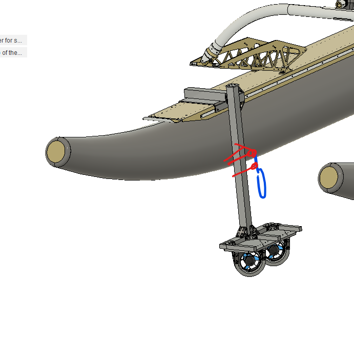
The thought process for this design is to integrate the hydrophone mounting onto the vectored front motor thrusters. This simplifies the design of the system as the propulsion superstructure can be utilized for the hydrophone mount. Greatest problem now is the proximity to the surface of the water
Rev 1, getting ideas down for a visual representation of the hydrophone mounting on the front vectored thruster’s vertical bar
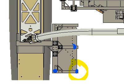
Rev 2, top view, deciding where to place the hydrophone

Rev 3, determining the hydrophone should be under the interface plate to enable the greatest chance of the hydrophone receiving the pings

Top view of the vectored motor mounts
The blue dots represent the potential hydrophone placement location.
The purple vectors represent the direction the water will flow.
The hydrophone will be placed to the side of the motor mounts to avoid the currents that the motors will generate
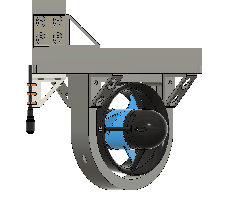
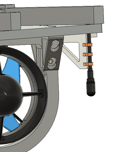
The design is a single printed part with zip ties holding the hydrophone to the printed part
Parts count:
1 AS-1 hydrophone
3 zip ties
2 ¼-20 1in long button head stainless steel screws
2 stainless steel t nuts
3d printed holder attached to the base plate
Biggest concern with this design is the hydrophone will most likely hit the trailer
Hydrophone mount on the inner section of the interface plate
Alternate view of the hydrophone mount on the interface plate


9/5/22 updated placement of the drone landing platform based off fitment on the actual boat
Colin Szeto
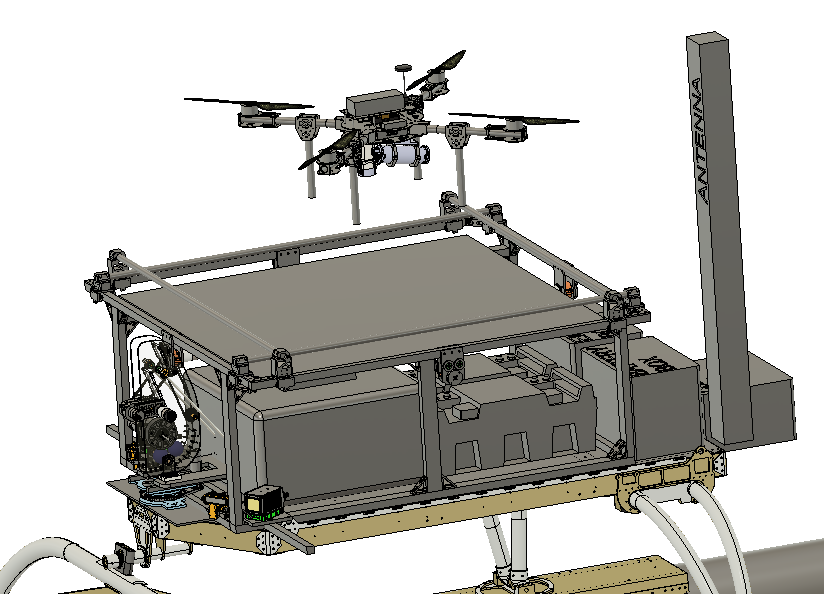
Updated placement of the drone landing platform.
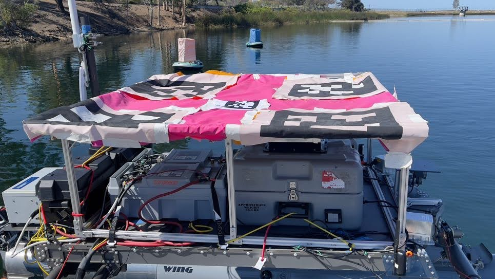
The left side of the frame is aft the right side of the frame is the forward part of the boat.
The drone platform is long enough to fit between the emo battery, battery for the electronics box, and the torqeedo batteries. However, this leaves very little space for the racquet ball launcher.
9/4/22 Designing the Downward facing OAK-D camera Mount
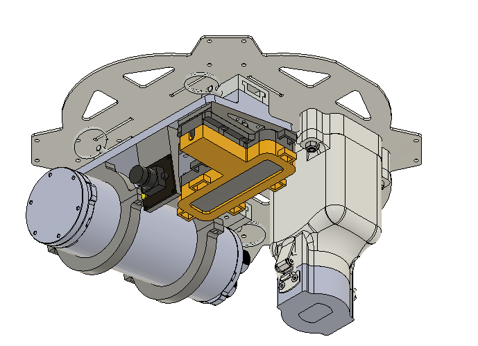 |
| Bottom ISO view |
 |
| Bottom view |
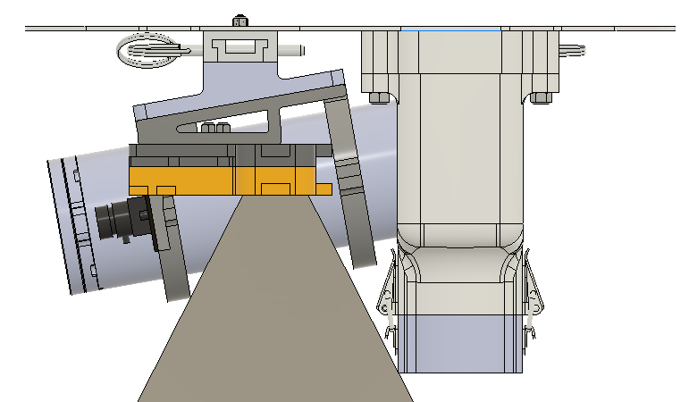 |
| Side view |
In the side view we see that the oak-d camera field of view is not blocked by the magnetic gripper.
9/4/2022 Design for the Hydrophone Arm
Lindsay Wright
ERAU boom arm is swing-style; we want a quick prototype that will interface with the WAM-V

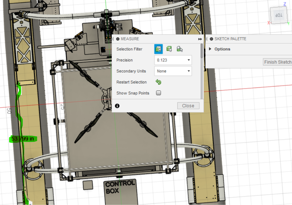
Distance between the back of the spring and the handles was measured to be 53.799" in the back-and-forth (k-hat) direction, which is our estimate of the length of Embrey Riddle's hydrophone boom arm:
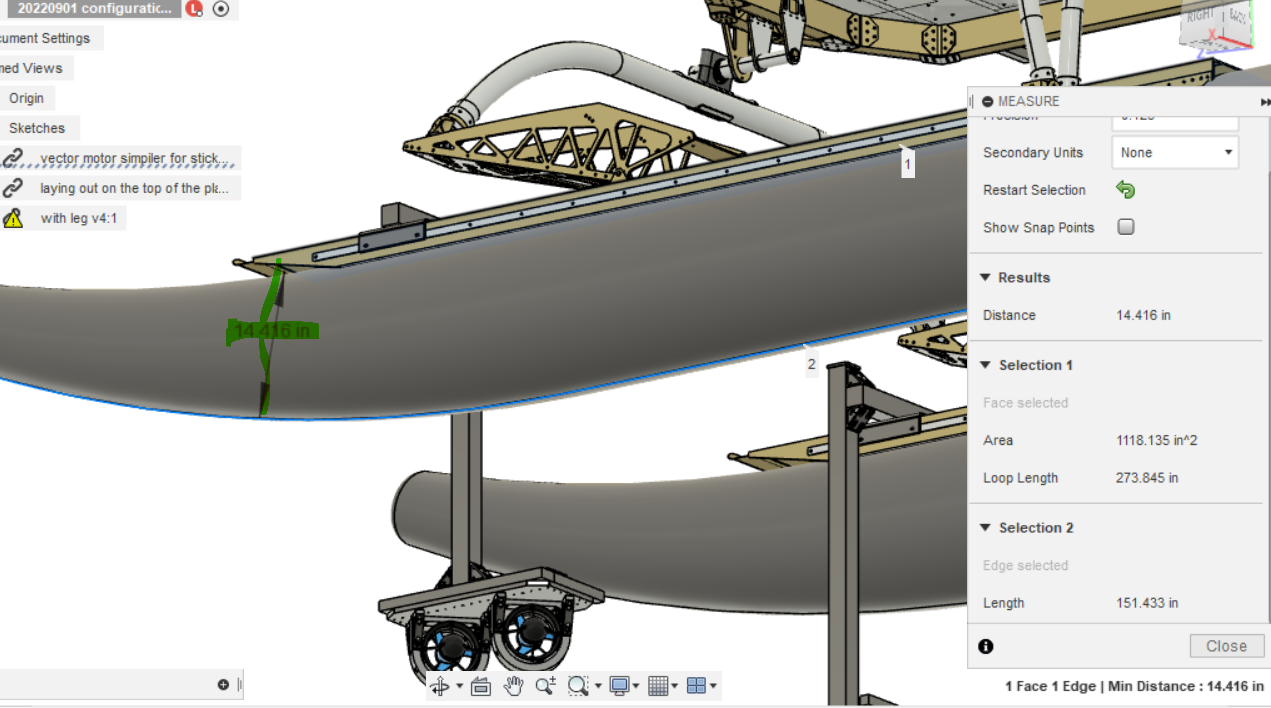
Pontoon height is roughly 14.416", but to be on the conservative side we will consider it as 15" (it wasn't measuring from top to very bottom as I hoped it would):
We add another 40"/1m to ensure the hydrophone is well under the surface
If we create a prototype mount similar to our T500 mount, then the minimum length of the boom arm is 58" (15+40+3 inches to account for the height taken by the mount)
This concurs with Embrey-Riddle's boom arm length
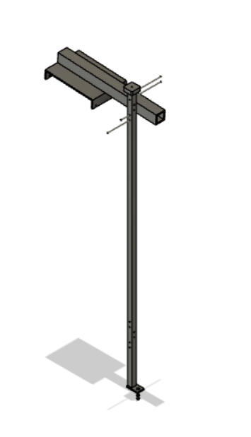
Therefore here is a prototype of a hydrophone boom based on Colin's T500 mount design.
Notes on parts:
rod is drilled .25" diameter with the intent of filling with threaded rods
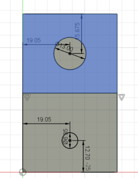
Mounting plate for hydrophone:
9/3/22 3D printing

Printing out the servo housing in ABS at UCSD printers, note the mounting holes will utilize screws threading the plastic rather than brass heated inserts

Magnetic latch in PLA at UCSD printers, note the mounting holes will utilize screws threading the plastic rather than brass heated inserts
9/3/22 Notes on the assembly of the claw

4.233 mm
Will have to cut down m3 16mm screw to 12 mm to have enough clearance
Alternative: 10 mm screws or revert back to using heated inserts and screws.

When knob rotates there is still clearance
9/2/22 Motor Guard for Cruise 2.0 thrusters
Colin Szeto
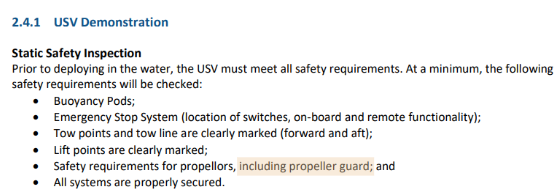
Re-reading the requirements over again we identified a propeller guard is required

This design consists of 5 unique parts. The intended manufacturing method is through cutting material with a laser cutter, cnc router, or water jet.
CAD to motor guard here
9/1/22 Dummy Proof Storage
Colin Szeto
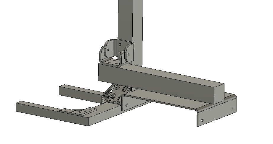
Thought process here was that the mount could pivot up. Utilizing bent aluminum plates with holes. Reduces the hard interface points between the vertical bar to the horizontal part from 3 2in by 2in angle brackets to 1 2in by 2in pivoting bracket.
For linear motion of deploying the thrusters we would still have to loosen the screws from the vertical bar and the pivoting bracket to enable lowering of the motor plate
9/1/22 Finalized version of Drone Landing Platform Structure
Colin Szeto
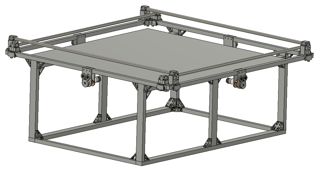
This section overviews the decision making on why 1020 construction was selected in creating the drone landing platform
Link to File here

The bearings intersect with the existing solution for mounting the 8020 cross braces on the bottom of the 8020 rail
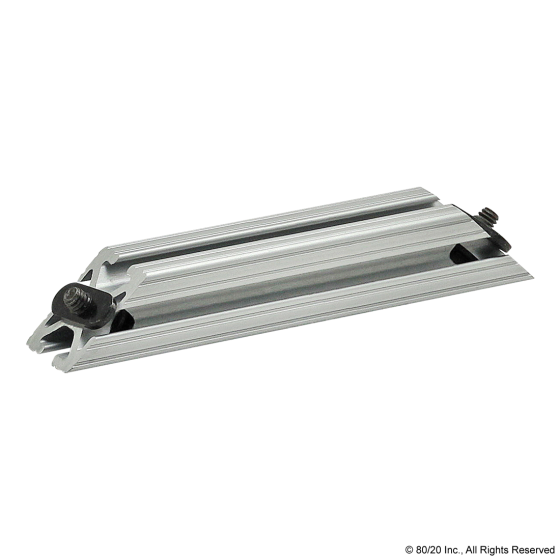
An alternative solution was to use the 8020 part number 2565
Part website here
However each of these angled profiles had a unit cost of 20 dollars. This would come up to a minimum of 160 dollars if we wanted to support the horizontal rails
An alternative solution was devised to utilize 1020 bars (1 in by 2 in) as the support
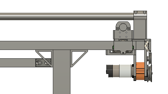
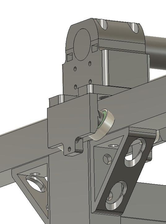
This usage of 1020 allows the carts to freely move along the bars with providing support the construction.
This top view illustrates the landing platform will be amply supported

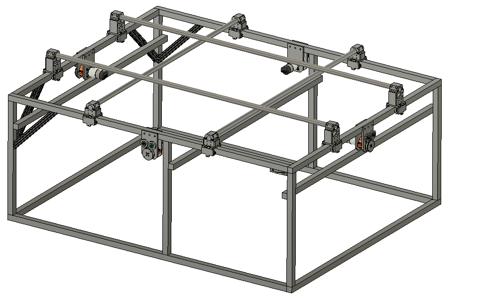
This triple bar configuration would not have provided ample support for the landing platform.
Parts list and supporting documents: here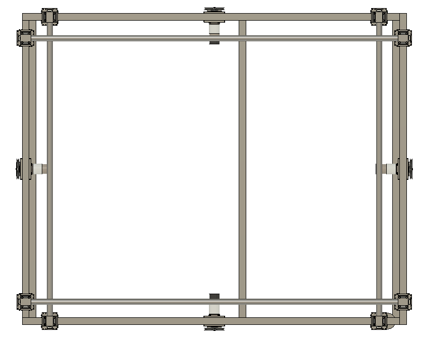
20230508 Tuning In the O-Ring Size
Parker handbook 4.3 Face Type Seals “Face type seals are sometimes rectangular. In designing such a seal to receive a standard O-ring, th...
-
20230103 Second Version of Camera Enclosure Using sealing m4 screws to mount oak-d onto back here Thinking about a male usb-c breakout board...
-
Dual Firing the torpedo Connect to one axle, out of phase by 90 degrees Potentially change this linkage to a CAM (would require spring to ...
-
Colin Szeto Objective was to verify the feasibility of the assembly and dimensions of the motor guard around the physical motor before laser...

