3/25/22 Creating a BOM from FUSION 360

In pursuit of creating assembly instructions for the drone landing platform our team ran into issues creating a concise BOM (bill of materials). In Fusion 360 when a component is mirrored it will be saved under a new name. This naming scheme has been discussed previously on the Fusion 360 blog here. You can see the naming scheme effecting the total quantities in the BOM in the drawing below: 
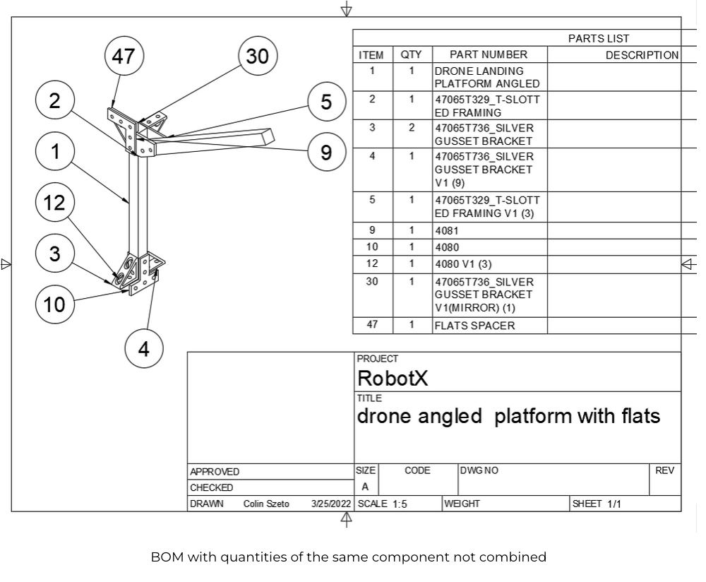
BOM

BOM with quantities of the same component not combined

In modeling the drone landing platform we mirrored many components to avoid having to import every bracket on every connection.
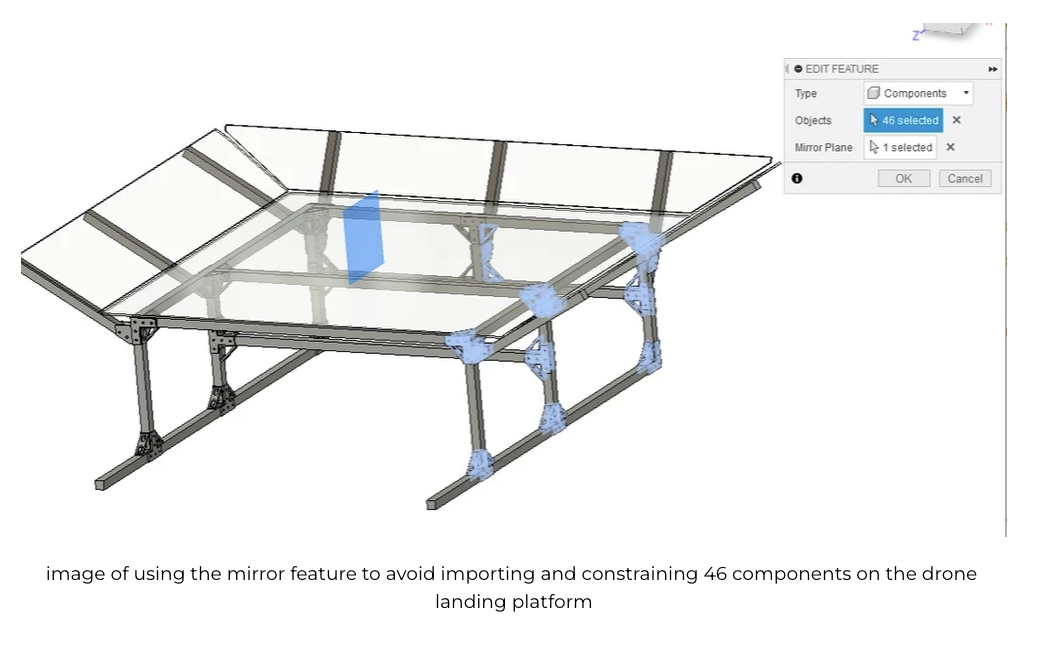
ISO view CAD

Image of using the mirror feature to avoid importing and constraining 46 components on the drone landing platform.

The easy fix to avoid the conflict in the naming scheme would be to not use the mirror function to populate the model with components. We needed to iterate quickly in CAD and importing every component would take too long.

Initially the team used google sheets to take the csv output from the BOM in Fusion 360 to sum up the quantities of equivalent parts. However, user error could effect the output of the part quantities as users had to ensure that the correct cells were selected to sum up.
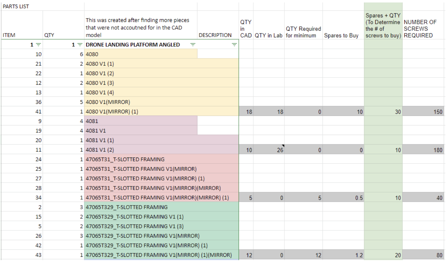
BOM Bill of Materials

Above is the spreadsheet grouping equivalent pieces, by creating a script we would eliminate these extra steps.

There were a couple of requirements:

  1. Account for both 8020 part numbers and McMaster-Carr part numbers
    1. 8020 part numbers are 4 numbers + letters (appending)
    2. McMaster-Carr part numbers are 7-8 character of numbers and letters
  2. Account for miscellaneous named components unique to the team and without part numbers
  3. Output as csv format for easy copy paste back into Fusion 360 drawings

The low level flow of the script:

  1. Opens up csv
  2. Line by line check if name is 8020 or McMaster
  3. Check if name is a miscellaneous part
  4. Remove extra bits of naming on the part and isolate part numbers
  5. Document part number and quantities in dictionaries
  6. Combine all dictionaries of part number and quantities
  7. Output as csv format

When all was said and done this script replaced about 20 minutes of potentially inaccurate work into a couple of seconds.

Find the scripts on GitHub here.

Future Improvements:

  1. Include table of both 8020 and McMaster-Carr part numbers to output both
  2. Consider having screw count included in how many screws are needed for each bracket to get estimate for hardware purchasing
  3. Integrate it into Fusion 360 as a script accessible within the UI
  4. Model each component individually in to bypass needed for the script

3/20/22 Drone Landing Platform Progress

Below are some images of one of the configurations of the WAM-V Drone landing platform that the team has ideated. 

Some of the requirements we set for the design were: 
  1. Limited to no machining required
  2. No alterations to the WAM-V platform 
  3. Provide assurance that drone will not slip off platform
  4. Allow space for mounting batteries and electronics on the platform away from the water line of the the WAM-V
These requirements were accomplished through: 
  1. Utilizing 8020 extrusions and brackets to create the landing platform
  2. Attaching the platform to the WAM-V with ratchet straps
  3. Including pitched walls on the edges of the platform 
  4. Elevate the landing platform to accommodate space for the electronics

ISO and top view of drone landing platform
Link to 3D model: Here

How the frame is mounted

Restricting sideways movement of the drone landing platform by placing extrusions onto the side rails

placements of the ratchet straps
Illustrating the front ratchet strap in CAD (secures platform onto WAM-V)

placement of the ratchet straps
Picture of the front ratchet strap that would secures the platform onto WAM-V

placement of the ratchet straps back
Illustrating the back ratchet straps that secure the drone platform to the WAM-V

placement of the ratchet straps continued
Illustrating the back ratchet straps securing the drone platform to the WAM-V IRL

Drone landing plate ISO view
Link to the interactive 3D model here

Drone landing plate side view
Side view of the drone landing platform without the WAM-V

Drone landing plate front and back view
Front and back view of the drone landing platform without the WAM-V

Drone landing plate bottom and top view
Top and Bottom view of the drone landing platform without the WAM-V

After getting the design reviewed by one of our mentors, Kevin Bower, we saw:
  1. Ratchet straps are not a good permanent solution as they can expand and contract. Usage of straps take away from the craftsmanship of the WAM-V. We can replace the ratchet straps with metal pieces or we can drill into the WAM-V platform and secure the drone landing platform into the WAM-V with bolts. 
  2. The pitched walls will provide little in securing the drone onto the platform. Actuators that clasp the drone when landed would be more effective in keeping the drone on the platform. This is similar to the Planck Aerosystems design for their line of products. 

Plank Aerosystems landing platform example
Plank Aerosystems Forward Imagery Project 
Link to demo video: Here

3/13/2022 Racquet Ball Launcher Progress

For "2.5.7 Task 7 - Find and Fling" teams are tasked with launching a racquet ball about 2 inches in diameter into a goal floating in front of the WAM-V vehicle. 


collapsed back arc

Current Configuration

  • Supports only one wheel for launching the racquet balls

  • Does not have a very aggressive tilting option (Note: the target will be below the platform of the WAM-V)

extended backing plate

Future Configurations

  • Use 2 counter rotating wheels to reduce spin & to ensure that the ball floats into the goal and has no chance of bouncing out

  • Very aggressive tilting options may not be needed as the target will be below the platform of the WAM-V


Link for determining gear ratio here


We got inspiration for hood design from the robot FRC team 1678 Citrius Circuits made in 2021. Below are screenshots of their shooter CAD side, front, top, and isometric views.

CAD of our current design with hood here

Using Onshape for their gear feature script is much more forgiving than the Fusion 360 gear script which has no option to revert and edit existing gears.

Video to learn about the feature script here

Feature script example can be found here

20230508 Tuning In the O-Ring Size

  Parker handbook  4.3 Face Type Seals “Face type seals are sometimes rectangular. In designing such a seal to receive a standard O-ring, th...